Photos courtesy of Glenn Davis. Text by Bill Miller.
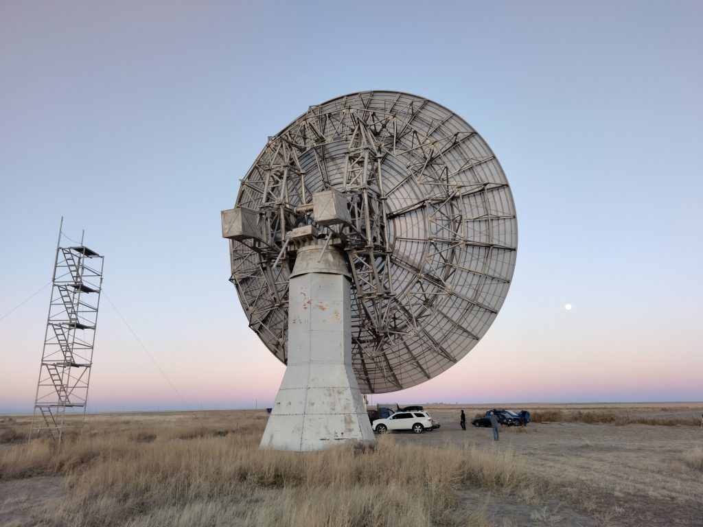
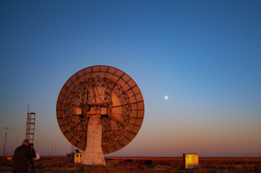
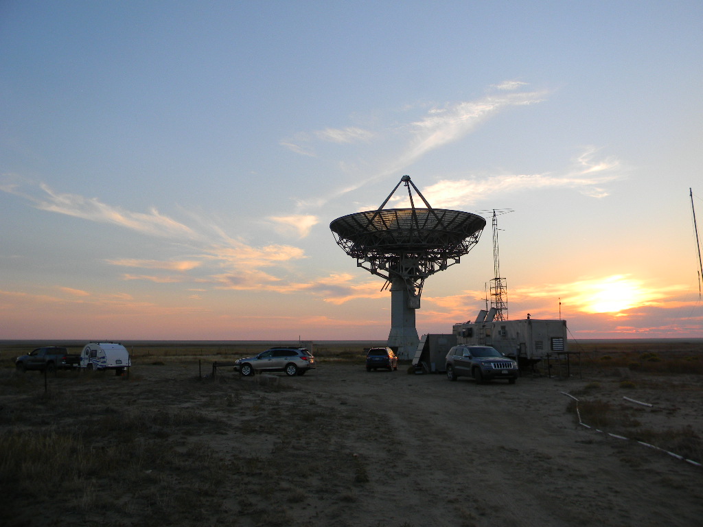
On Friday afternoon October 14, 2022, we prepared the 60-foot dish antenna for the weekend’s Moonbounce communications operations in the ARRL EME contest.
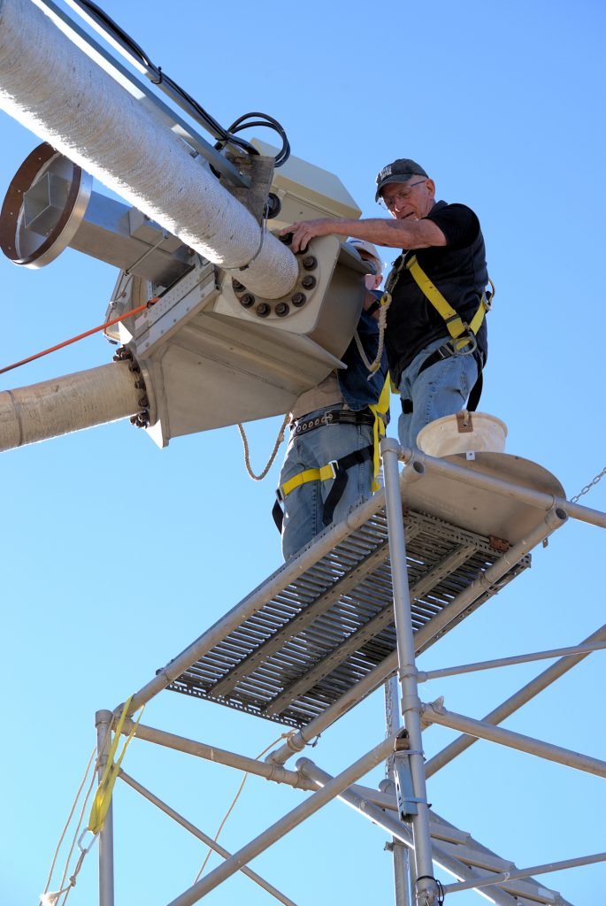
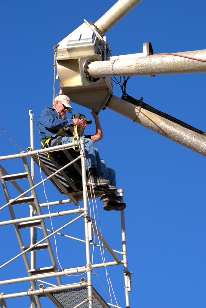
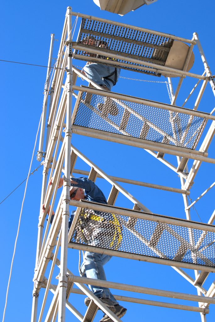
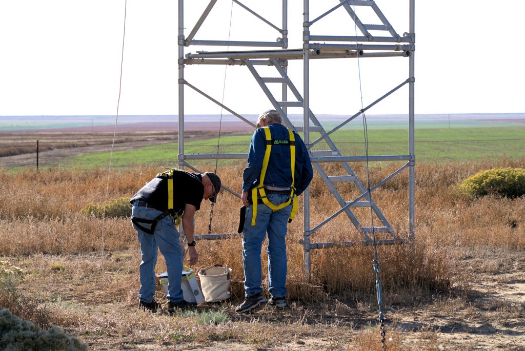
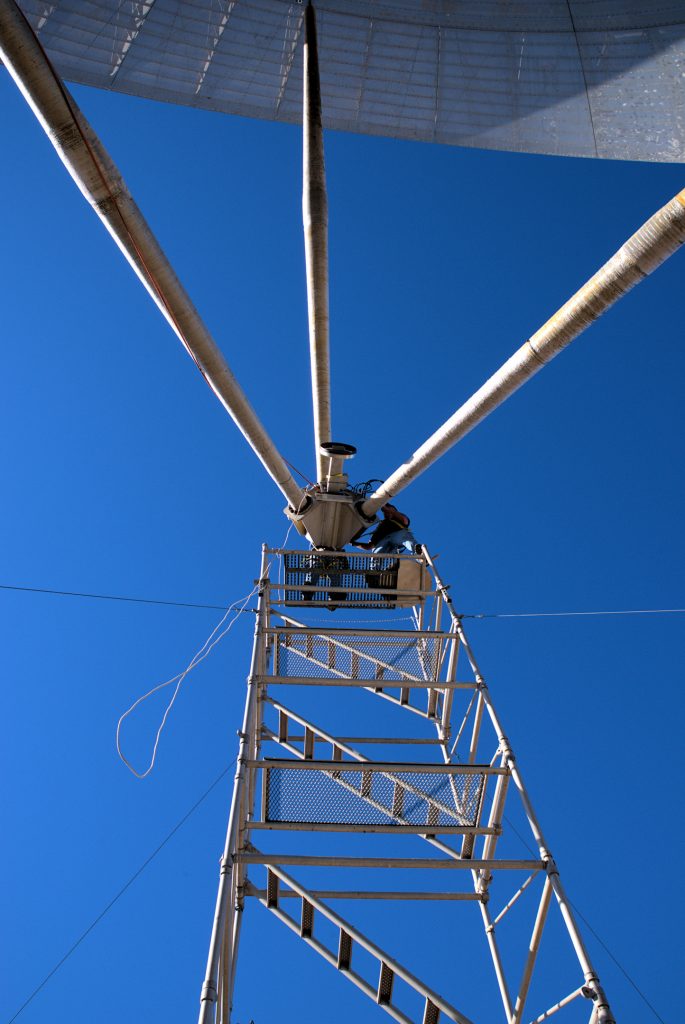
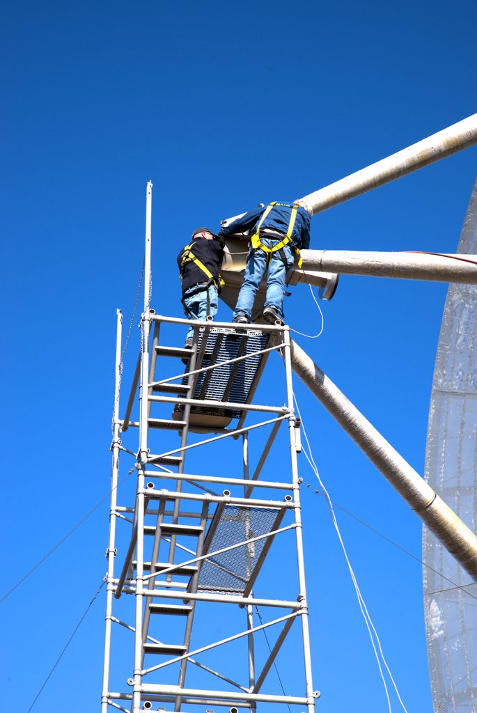
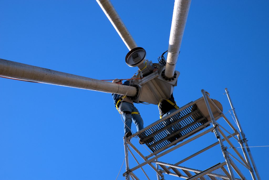
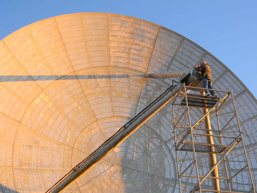
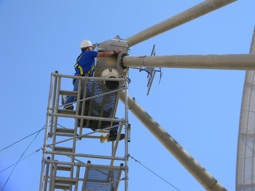
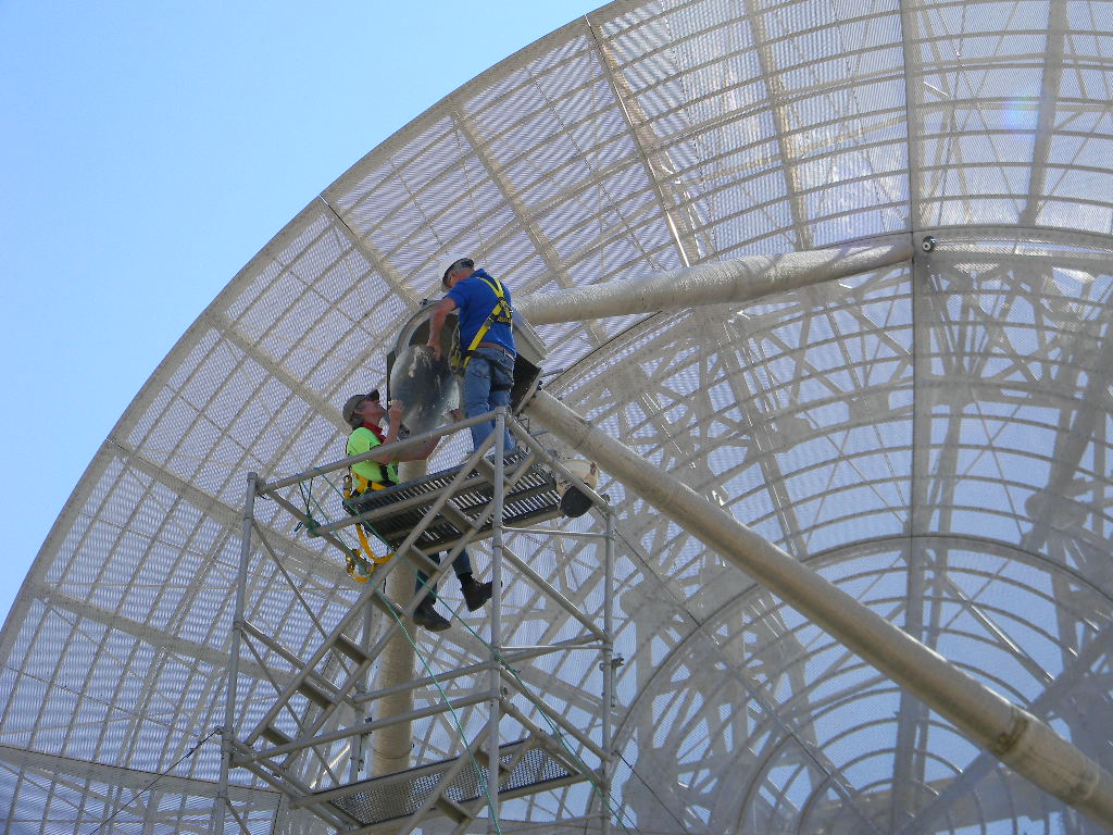
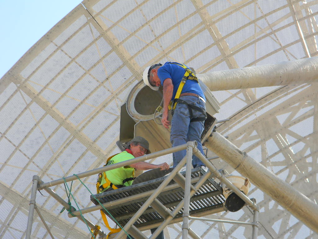
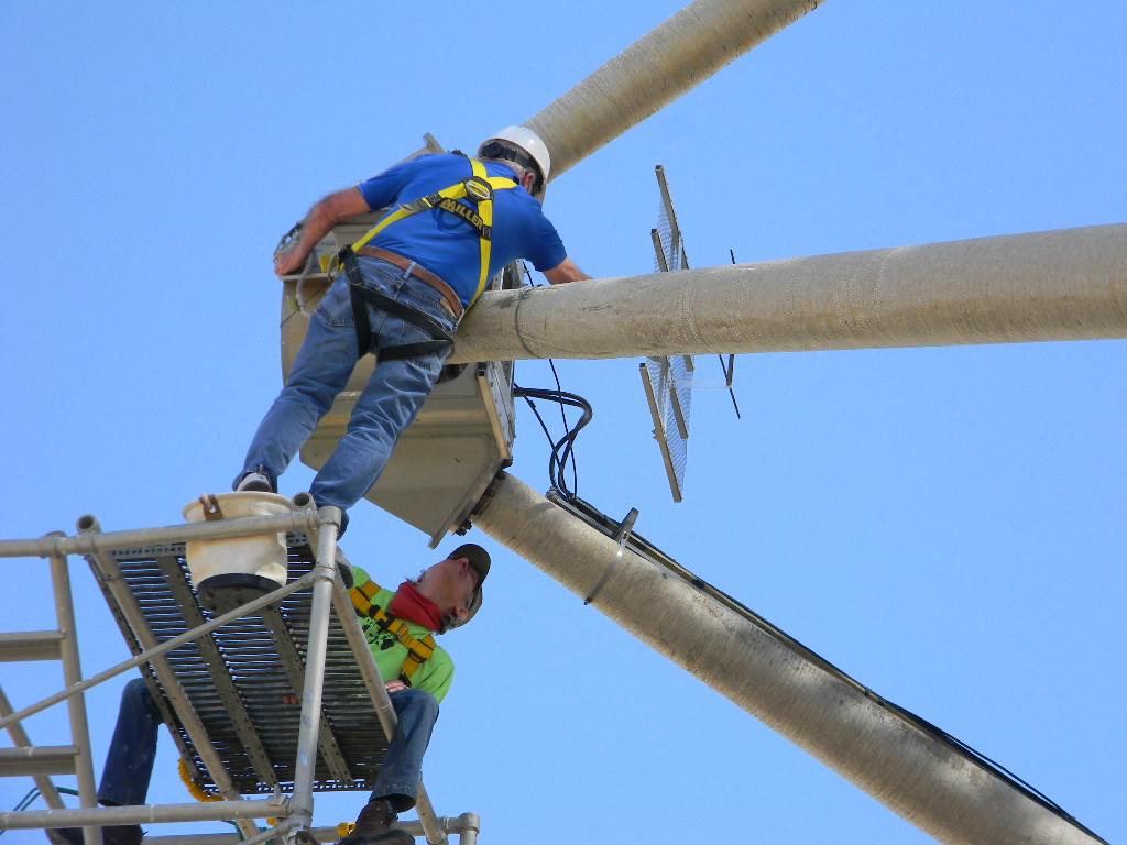
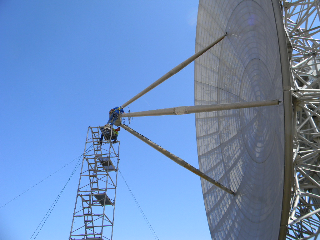
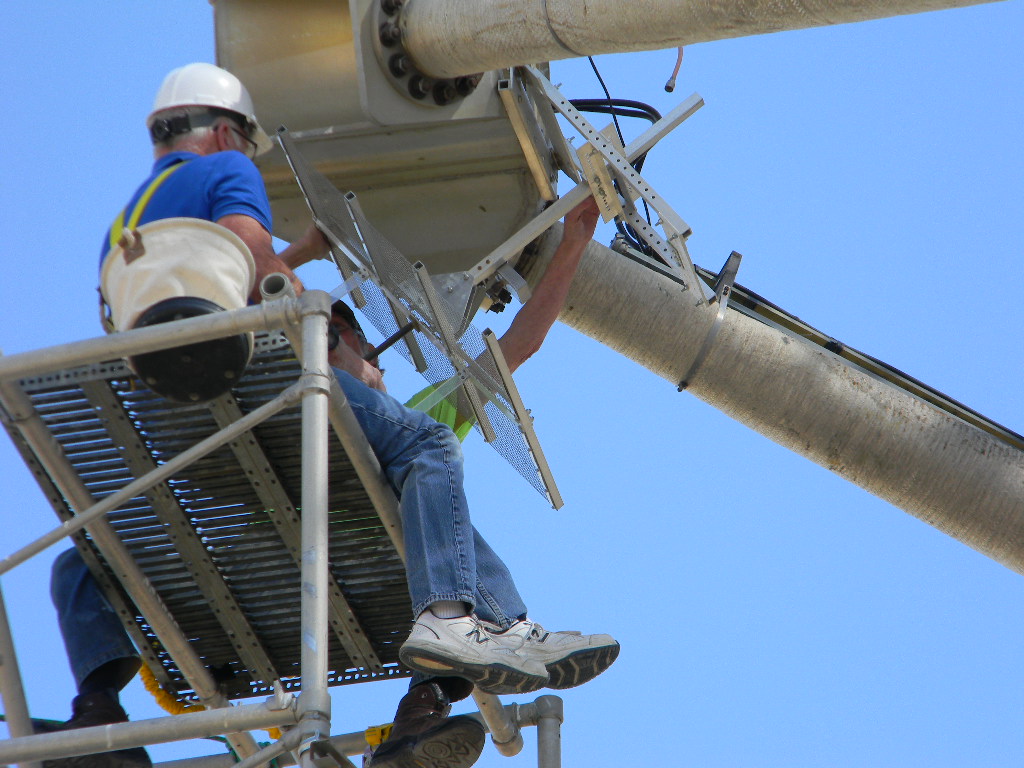
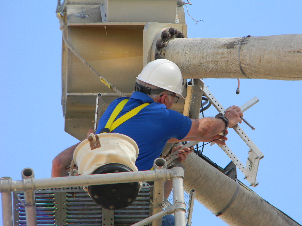
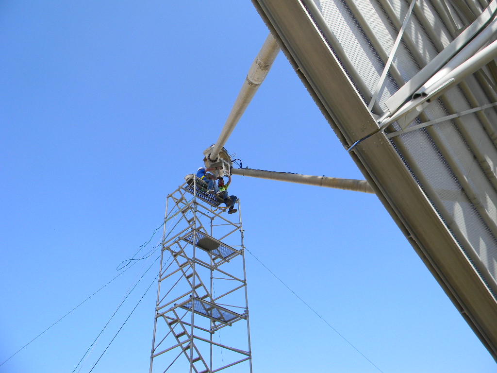
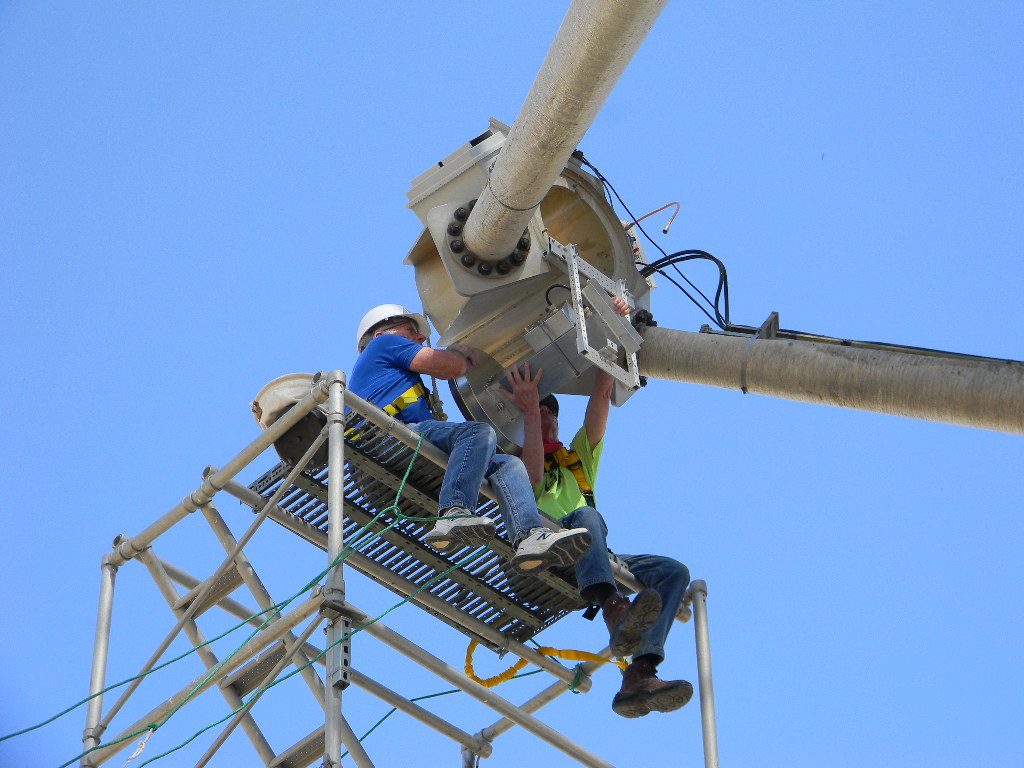
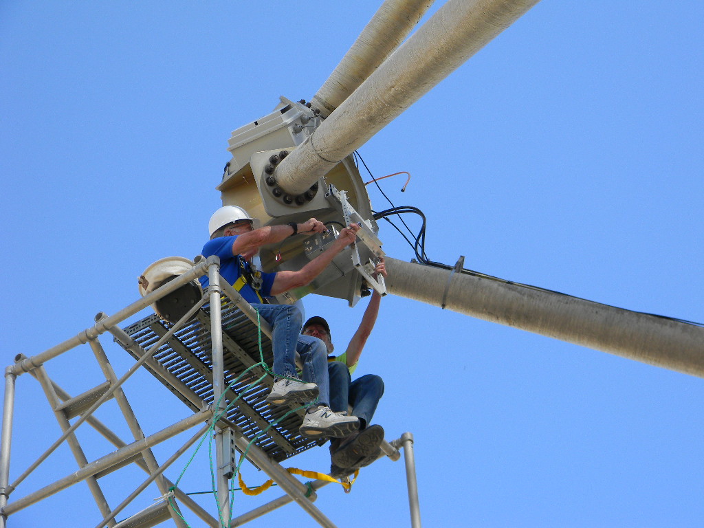
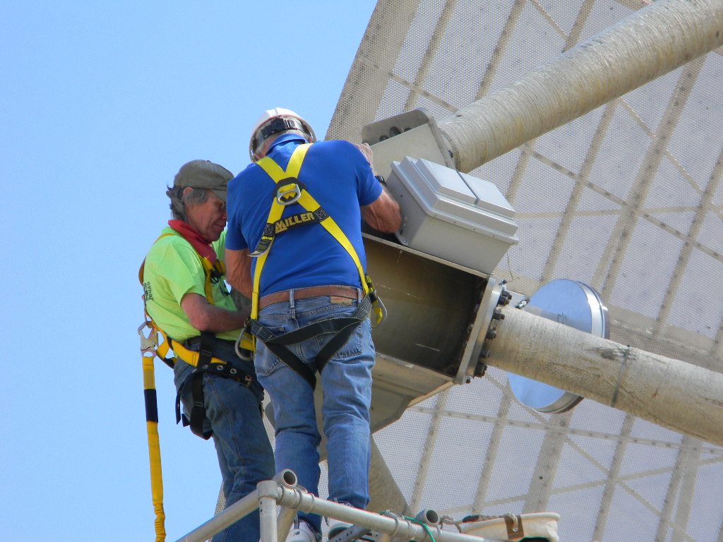
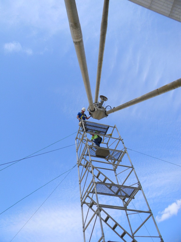
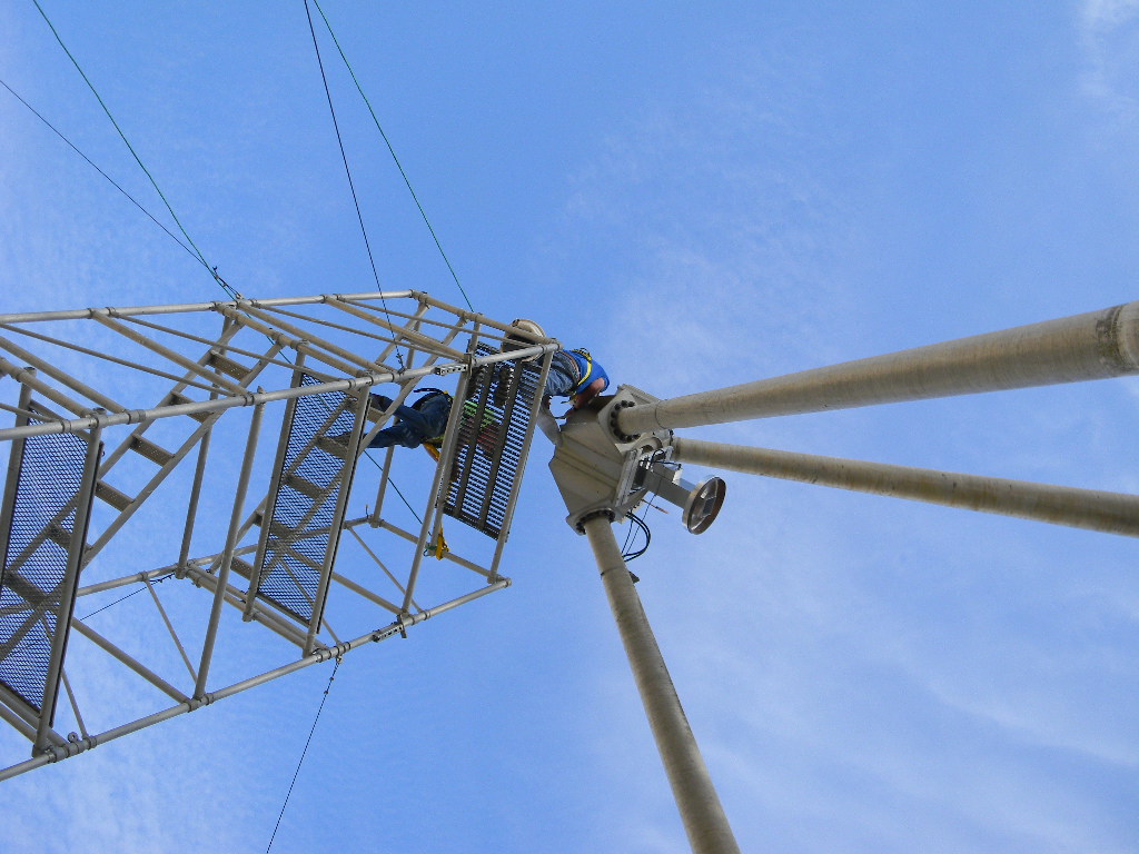
Glen Davis updated the tracking software, checked the callibration of the mount and helped as ground crew and photographer. Meanwhile Ray Uberecken and Bill Miller climbed the scaffold and changed the feed from the 437 Mhz antenna to the 1296Mhz antenna. They also installed Ray’s 180 watt amplifier at the antenna feed point and checked the system reception from Ray’s Calhan residence beacon.
Deep Space Exploration Society will support the Japanese OMOTENASHI Cube Sat Moon lander, by attempting to receive and record its UHF downlink signals enroute to the Moon and after landing. OMOTENASHI is a project created by the Japanese space agency JAXA Amateur Radio Club, and is one of ten Cube Sat satellites on the NASAArtemis 1 lunar mission.
Several hours after Artemis 1 boosts from an Earth parking orbit to a transfer orbit to the Moon, OMOTENASHI should deploy. After 6 days the OMOTENASHI will separate into an orbiter and lander, and the lander will make a hard landing on the Moon. The lander is designed to survive and then transmit signals.
This was our most successful EME season to date, not just in the number of contacts we made, but in the participation of our members, in successfully using a digital mode for many contacts for the first time, and with our equipment working well with no trouble. And we are learning from our experiences.
For our December weekend we had Gary Agranat WA2JQZ and Ray Uberecken AA0L operate through the whole weekend. We also had Jim Burnett WB0GMR, Flyod Glick WD0CUJ, Bill Miller KC0FHN, Glenn Davis, and Marc Stover. Jim got his first experience operating EME, making some of the digital Q65 contacts Friday night. Floyd, Bill, and Glenn stayed Friday night. Marc was there both nights to make time lapse movies of the antenna tracking the Moon. Glenn ensured our tracking system was working well. Everyone had a chance to call CQ on SSB and to hear their voices reflect back from the Moon 2 seconds later.
Moon bounce is communicating by sending signals to the Moon, and reflecting those signals back to Earth to anyone else who has visibility of the Moon and the necessary equipment. With the Moon’s distance a quarter of a million miles away, traveling at the speed of light, the signals take about 2 seconds to make the round trip journey. And the signals are significantly weakened by traveling that long a distance. With the Moon traveling at a different velocity from one’s location on the surface of the Earth, there also is a Doppler shift to compensate for. Moon bounce communications therefore can be quite a technical challenge. Reliably copying the weak signals can also be a challenge. With our large 60-foot dish antenna, our group is fortunate to have an excellent capability to meet all these challenges.
Because Moonrise was at about the time of sunset (as it was on the November weekend), our EME operation was essentially all over night, with a short period available also after sunrise.
We operated on the 23 cm band (1296 Mhz). We operated Morse Code CW, SSB voice, and Q65 digital mode. More about our technical setup later.
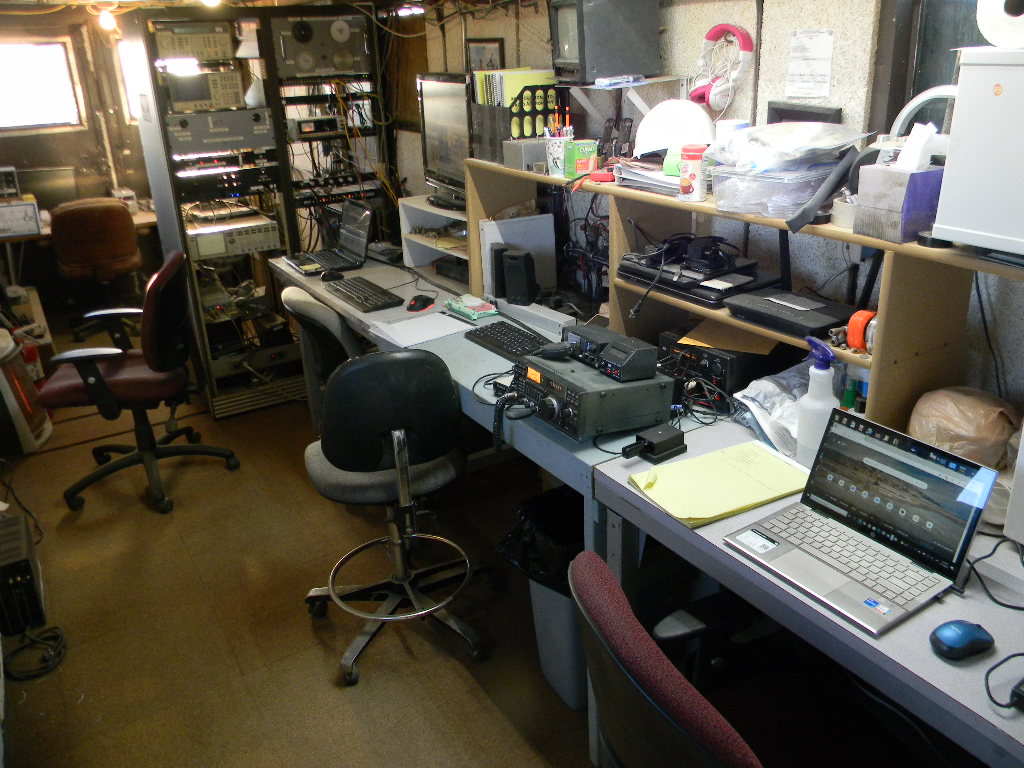
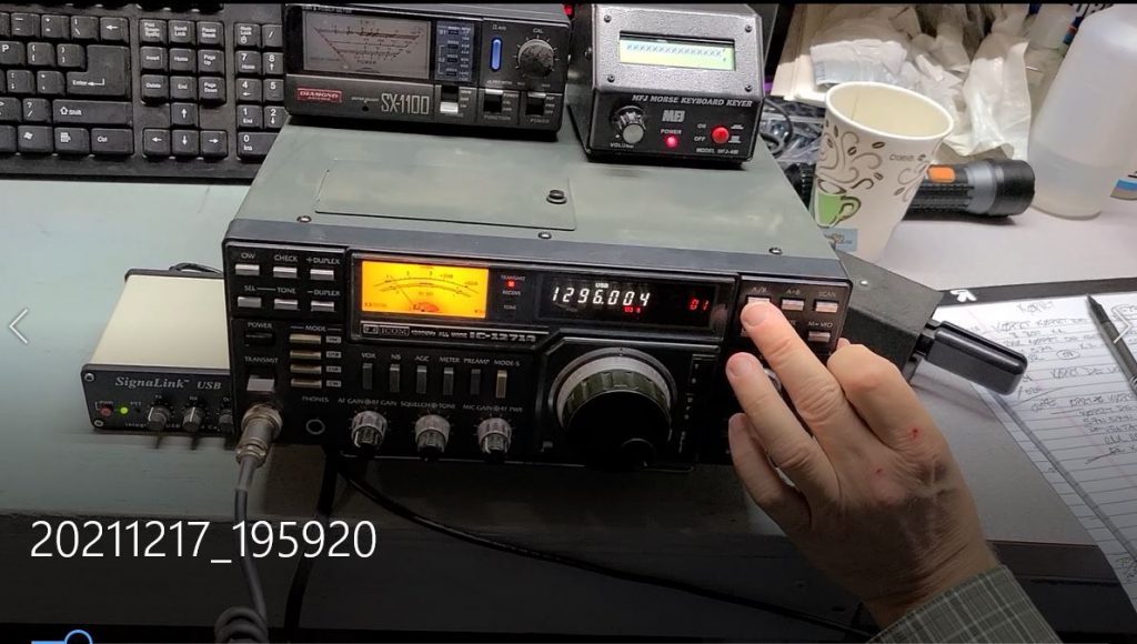
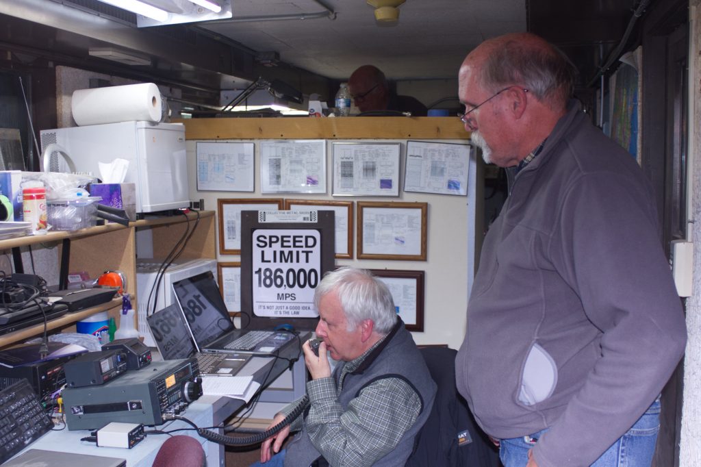
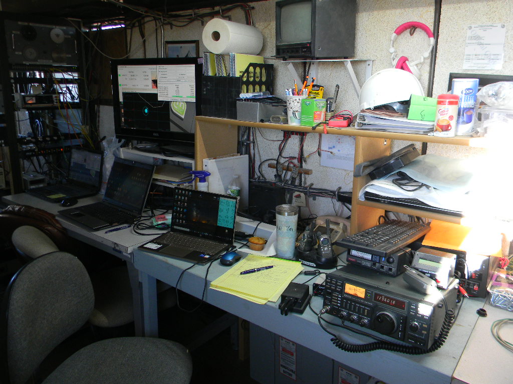
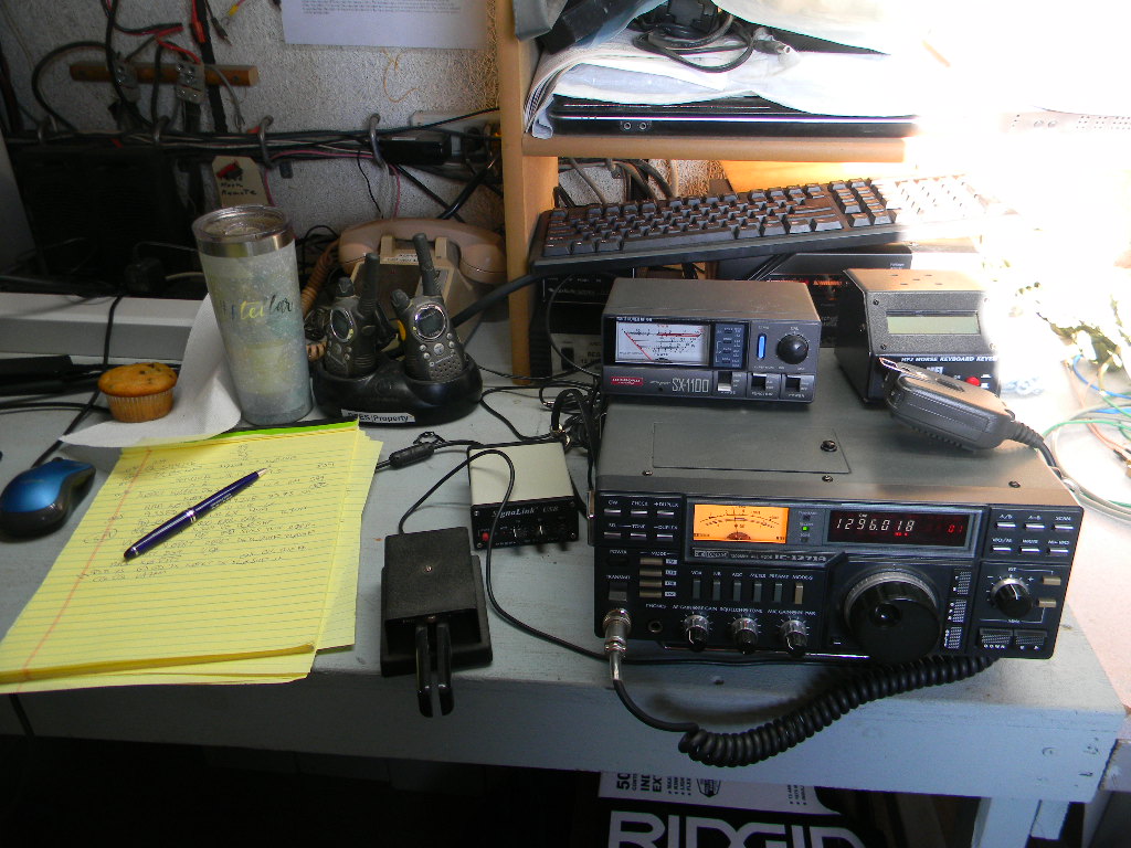
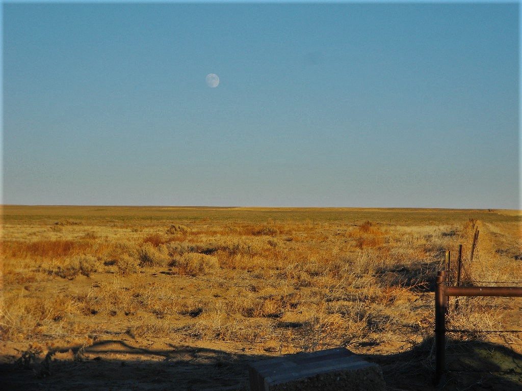
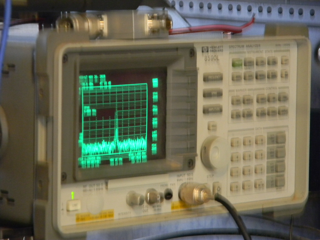
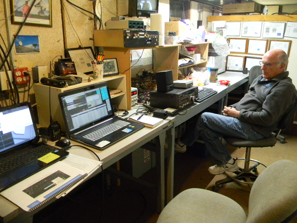
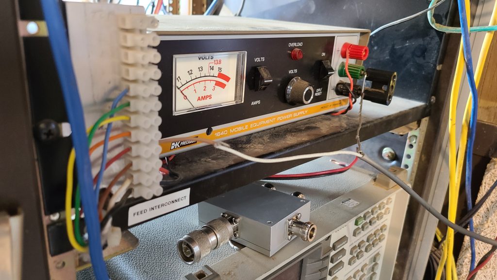
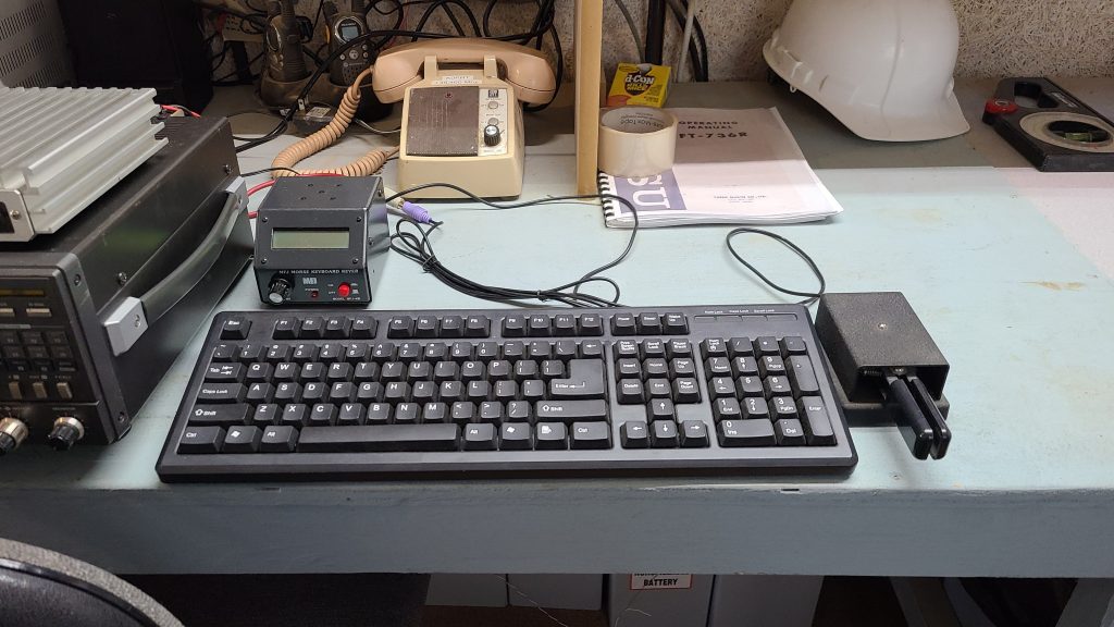
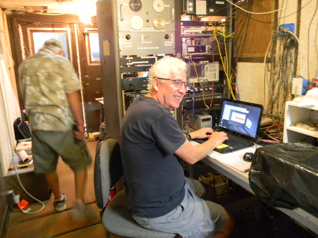
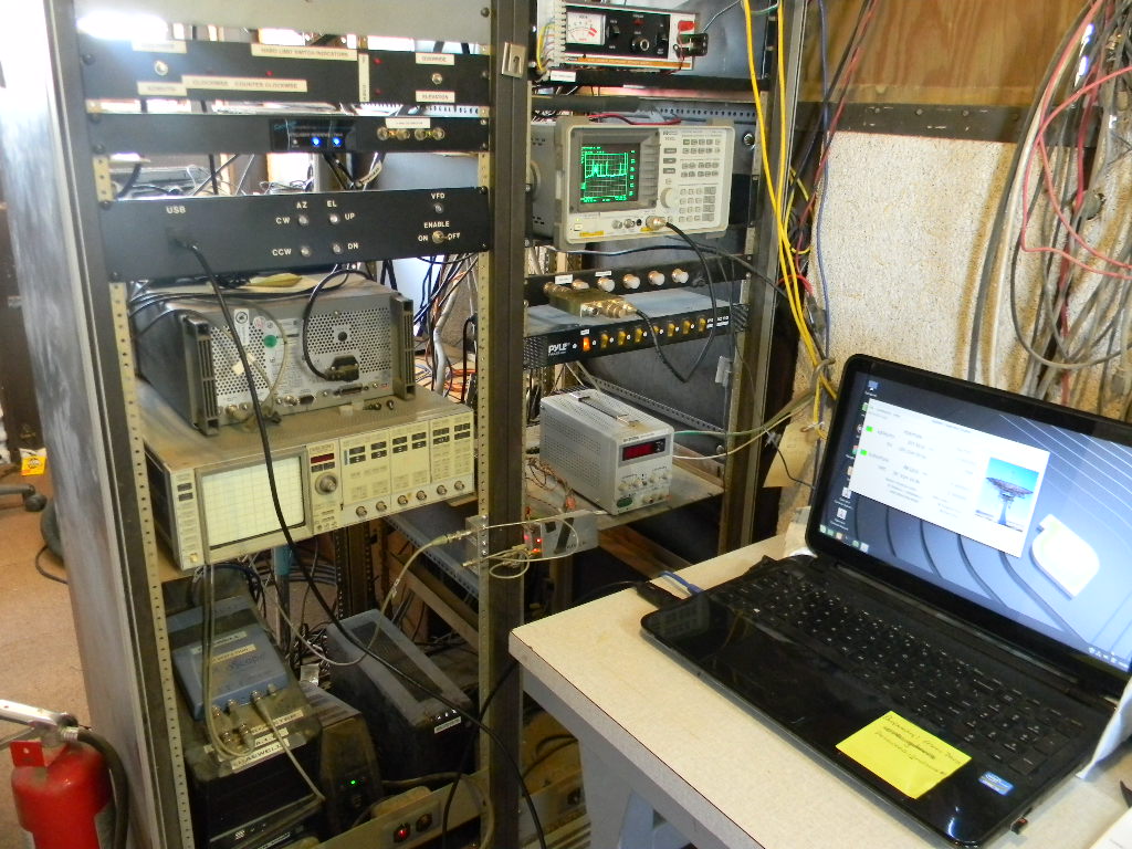
Friday evening, the Moon rose shortly before the 0000 UTC contest start time. We pointed our 60-foot antenna to the Moon and started tracking as we waited. (Photo by Gary Agranat WA2JQZ)Moonrise Friday evening (Photo by Gary WA2JQZ)Our operation setup in the trailer. Our transceiver was an ICOM IC-1275A. We sent Morse Code CW with a keyer set to 16 words per minute. (The keyboard could also be used for sending Morse Code, but that wasn’t used.) Antenna tracking was set and monitored with the computer and display at left. We monitored our signal output with the power supply meter and scope display located in the rack further left. The laptop at right was used for logging. Off to the right a separate laptop was used to control making the digital Q65 contacts.
On our December weekend we made 47 EME contacts. Added to our November weekend operation, that brought the total number of contacts to 92. This compares with the 50 contacts we made for the contest last year.
Of the 92 contacts, 54 were CW (Morse Code), 2 were SSB phone, and 36 were in the new Q65 digital mode. 53 contacts were to Europe, 33 to North America, 3 to South America, 1 to Australia, 1 to the Philippines, and 1 to Asia (Japan). We contacted 22 unique DXCC entities, 16 states, and 3 Canadian provinces.
For the November weekend, Dan Layne AD0CY got our Q65 digital mode working and made 2 contacts then. On the December weekend, Jim WB0GMR operated Friday night and made 8 Q65 contacts. Gary WA2JQZ stayed for the operations on both weekends and made the other contacts (CW, SSB, and Q65) with the help of Ray AA0L.
For this year’s contest we experienced no significant technical problems. That enabled us to start operating as soon as the contest time started and as soon as we had a signal path to the Moon. The operations for both weekends went smoothly and with a relaxed tone.
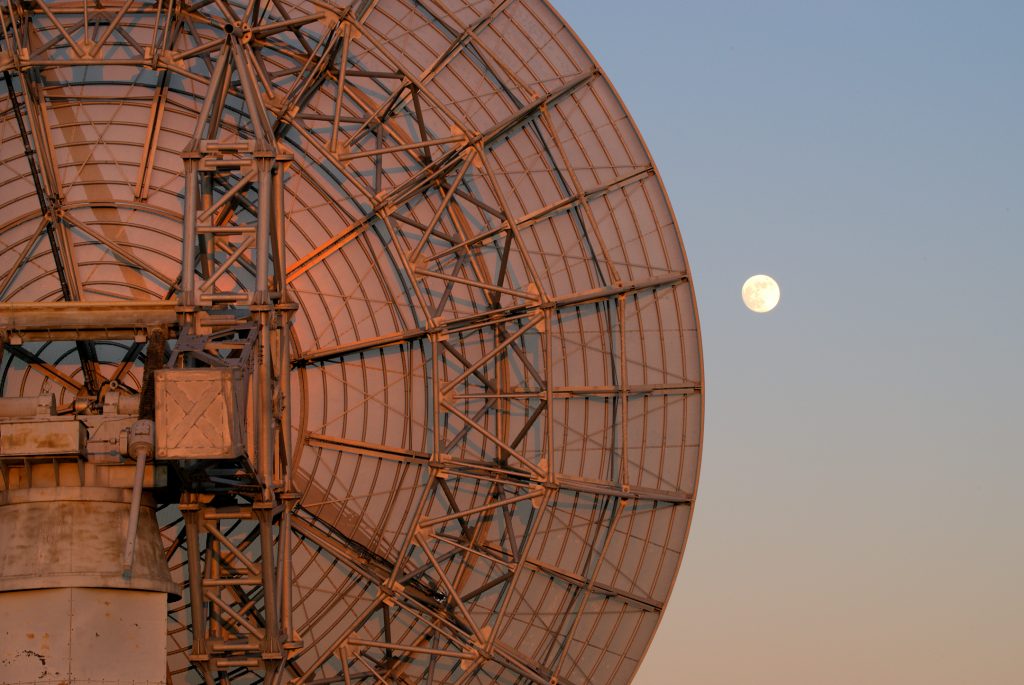
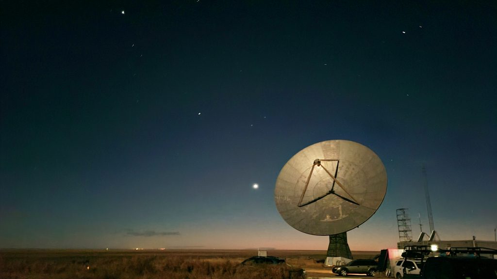
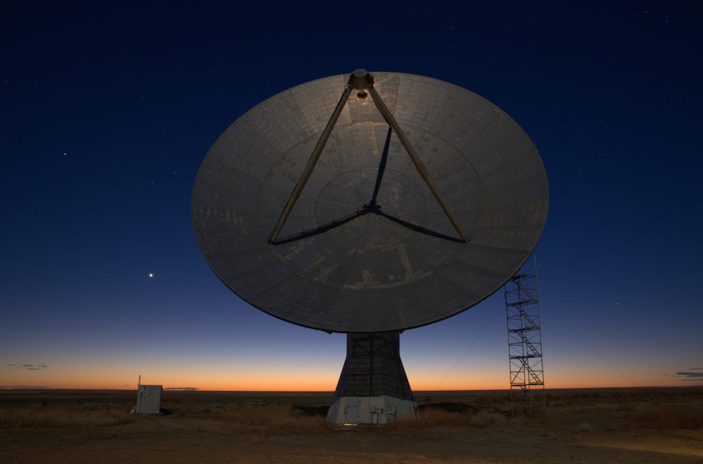
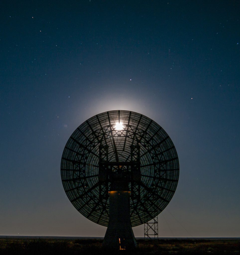
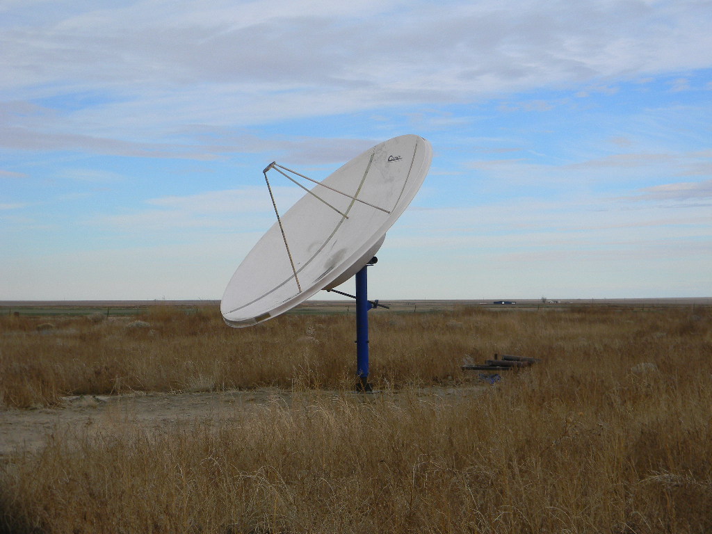
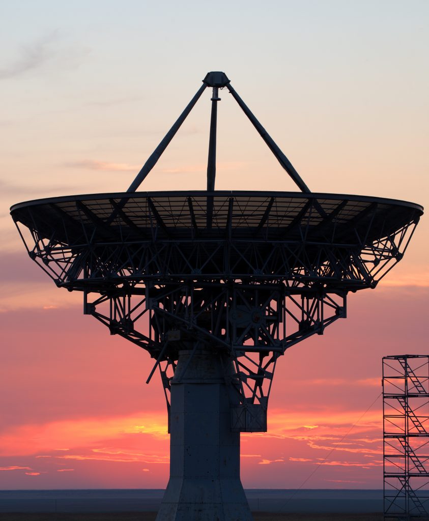
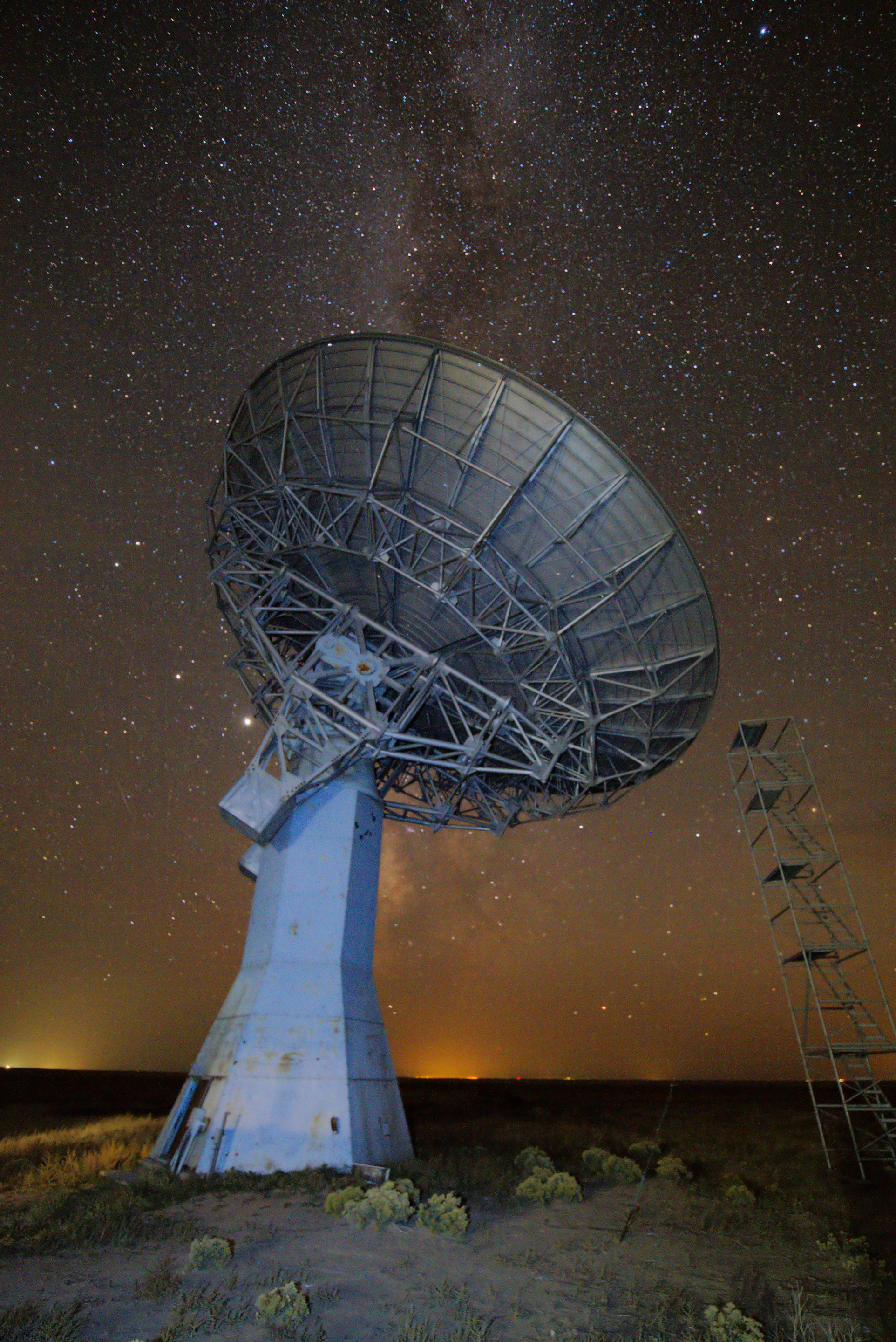
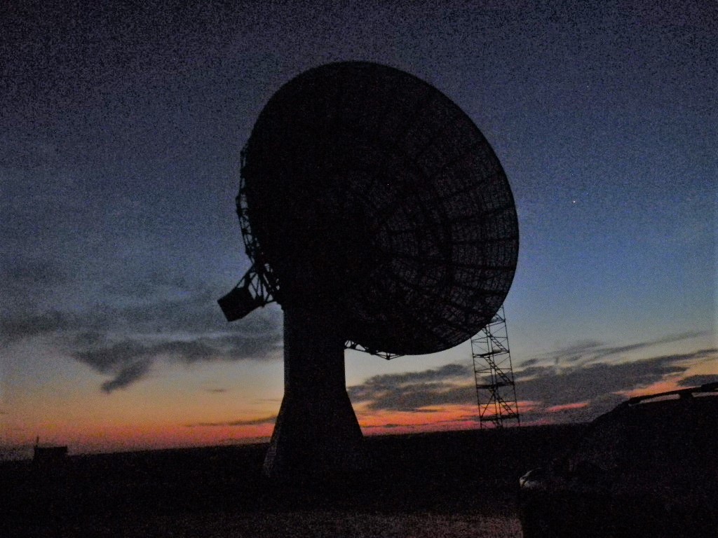
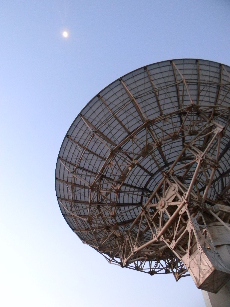
Our 60-foot dish antenna bathed in full moon light as it tracked the Moon during operation Friday night. The planets Venus, Saturn, and Jupiter (lower center to upper left) brightly lit the western sky after sunset. (Photo by Bill Miller KC0FHN)Our 60-foot antenna tracking the Moon. (Photo by Glenn Davis)
Ray AA0L contributed this technical description: The moonbounce equipment this year consists of an ICOM IC-1271A with a built-in low noise preamp (about 1 dB), a VHF Design 150 Watt amplifier at the feed, a Tokyo High Power intermediate power amp with built in Gasfet preamp, VHF Design .3 dB nf, 30 dB gain preamp at the feed and a KL6M feed with a choke. All this provides a noise figure of 0.4 dB with an overall gain at the feed of >40 dB. We have more than sufficient gain in both directions to overcome the 200 or so feet of feedline from the trailer to the dish feed.
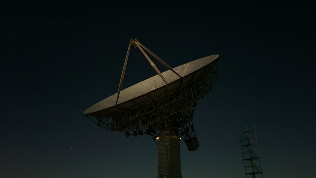
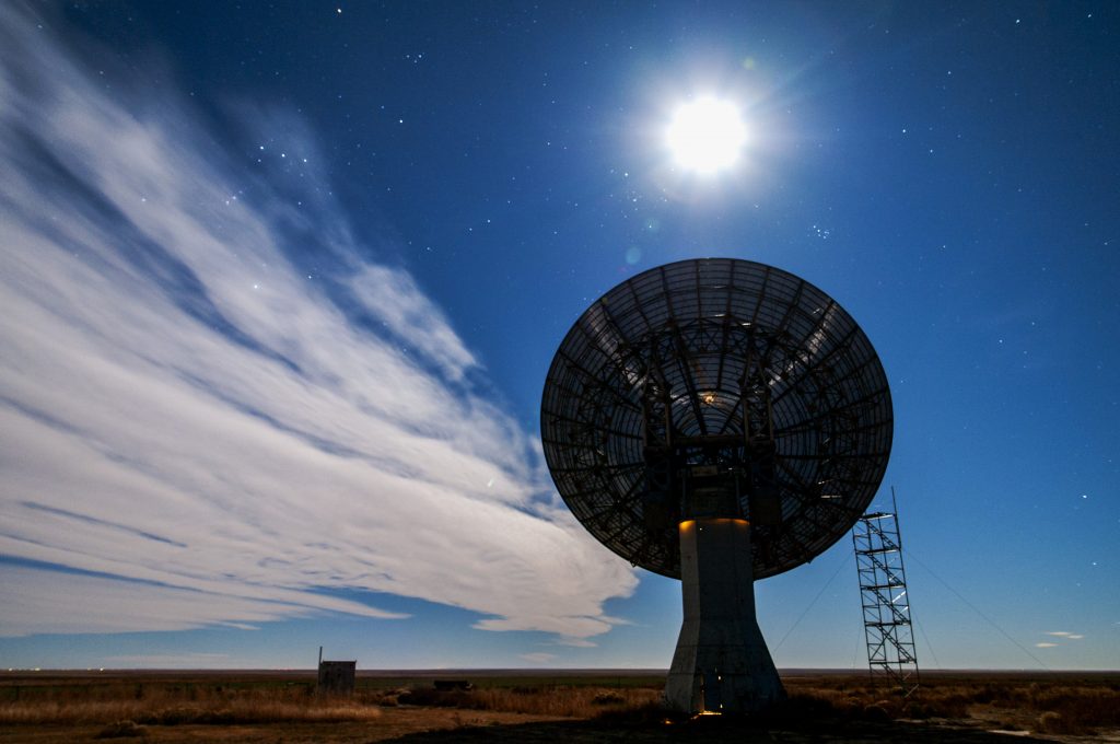
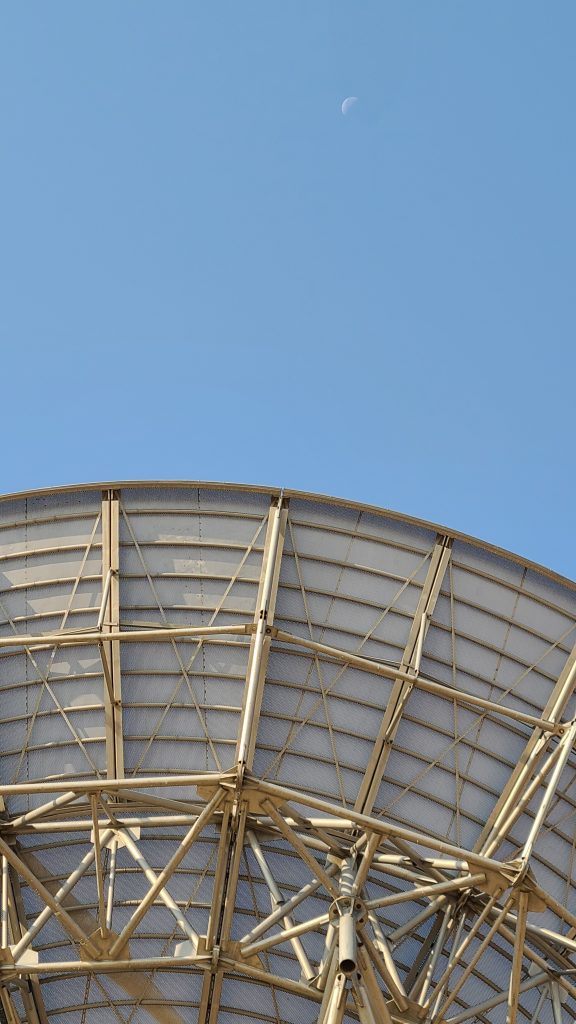
Our 60-foot antenna tracking the Moon Friday night. (Photo by Bill Miller)
On Friday night we tried to get in as much Morse Code CW contacts as we could. We switched to digital Q65 when we had contacted most of the CW contacts we could hear at a given time. Through the night we alternated back and forth. We also occasionally attempted SSB voice.
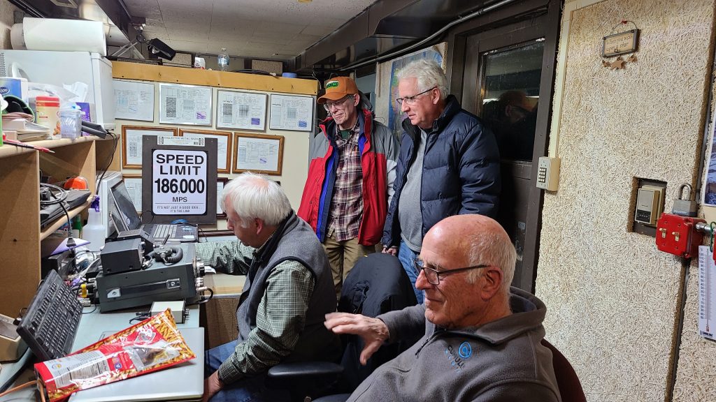
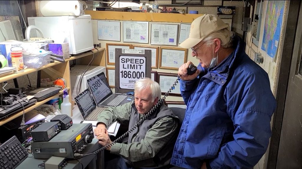
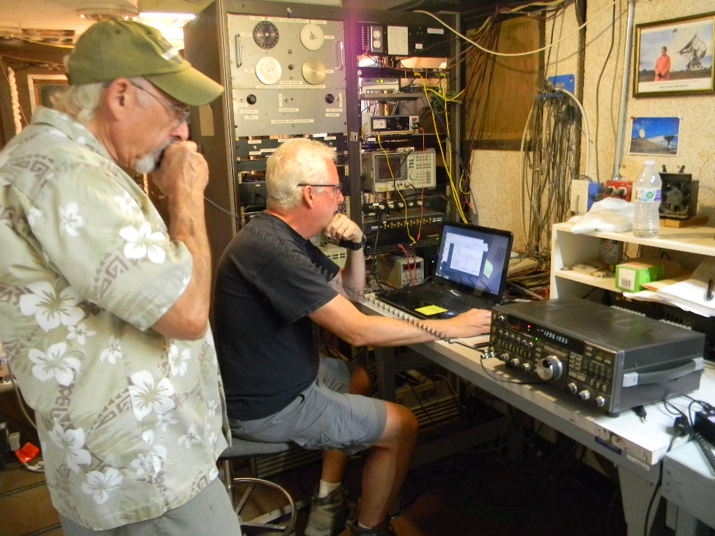
Gary copying Morse Code CW during a contact, with (L to R) Floyd Glick, Glenn Davis, and Ray Uberecken. (Photo by Bill Miller) Due to the Doppler shift, we had a gap between transmit and receive frequency by as much as 3 KHz. We switched between the two frequencies by using the transceiver’s two VFOs. We used the WSJT software by (W1JT Joe Taylor) to continually calculate and display the frequency difference. (Still from a video by Bill Miller)Jim WB0GMR (standing) and Gary WA2JQZ operating SSB. Jim later operated digital Q65 and made 8 contacts. (Photo by Floyd Glick)Bill Miller KC0FHN calling CQ.
On Saturday morning we determined when the Moon would rise in Japan and in Australia. We stayed awake for that, and when those times came, we searched for those stations. That’s how we immediately found our Japan and Australian contacts, as soon as they had a signal path. We got them in time before the pileups that followed. When we couldn’t hear any additional stations, we went to sleep.
We had an unexpected power failure late Saturday morning, after the Moon had set and we were taking a break. The cause was eventually traced to a pigeon that had short circuited the transformer where the electric power comes into the site. We called the local utility, and after a couple of hours they reset the circuit breaker on the main county road. This was unfortunate for the pigeon. But fortunately for us this didn’t happen during our EME operation, and didn’t disrupt us.
As we anticipated, most of the stations we heard on CW on Sunday night were ones we had already worked. Therefore on Sunday night we concentrated most of our efforts on digital Q65. We made most of our digital contacts then.
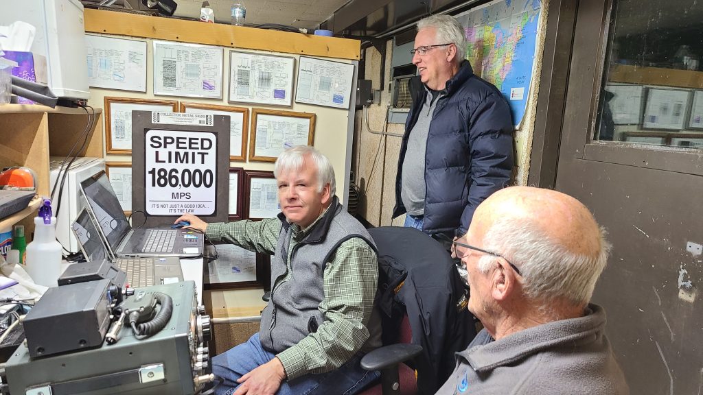
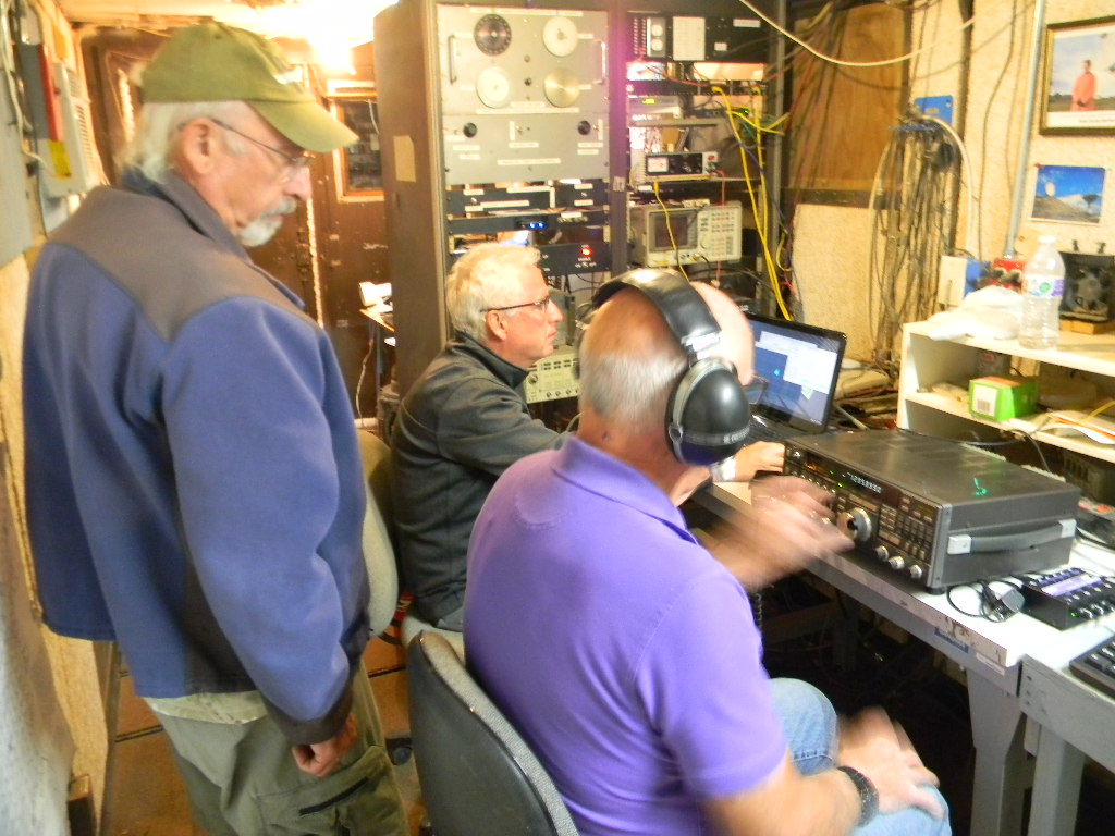
Gary, Glenn, and Ray. Digital Q65 operating. (Photo by Bill Miller)
On Sunday morning after the Moon had set, as we woke up and wound down and had coffee, Gary made some HF FT-8 digital contacts on the 15 and 20 meter bands. A portable multi-band end fed antenna was extended from the trailer to the service tower. And the contacts were made on a Yaesu FT-950. The bands were open to as far as Europe and Japan. This gave us a chance to get on the air on the more traditional ham bands, and to be part of the rest of the ham radio community. Over 50 FT-8 contacts were made.
The Yaesu FT-950 operating HF FT-8 and the End fed antenna extended to the service tower. (Photos by Gary Agranat)
This was our most successful EME operation to date. We made more contacts, our equipment worked well as expected, we had increased participation, we developed our experience further, and we all enjoyed the experience. Certainly hearing one’s voice or signal come back from the Moon 2 seconds later is an experience one doesn’t forget. This should give us a basis for doing more EME operations, better, and more times than just for the contest.
This year several members also devoted their efforts to photographing. Marc Stover’s time lapse movie work and Floyd Glick’s lunar photography follow.
Mark Stover devoted all of Friday and Saturday nights to record time lapse movies of our dish antenna tracking the Moon, from Moonrise to Moonset. He used several cameras, capturing several perspectives, and several aspects of the antenna’s and sky’s motions. These are still images from photographing. These are followed by a one-minute movie he edited together. The temperature both nights dropped to the teens F. Marc wore an exposure suit to keep warm.
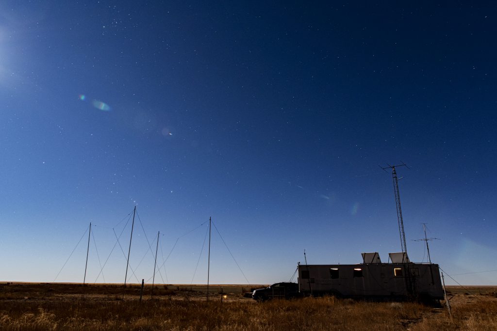
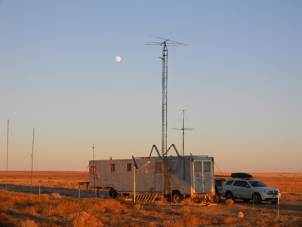
MoonriseOur operations trailer K0PRT at night. The constellation Orion is rising in the southeast.Moonset with the antenna tracking.A still-image from Mark’s movie, as the Moon nears the western horizon before dawn, with the antenna precisely tracking it. The constellation Orion is to the left of the Moon. The tight Pleiades cluster is to the right. The Moon itself is in front of the constellation Taurus.
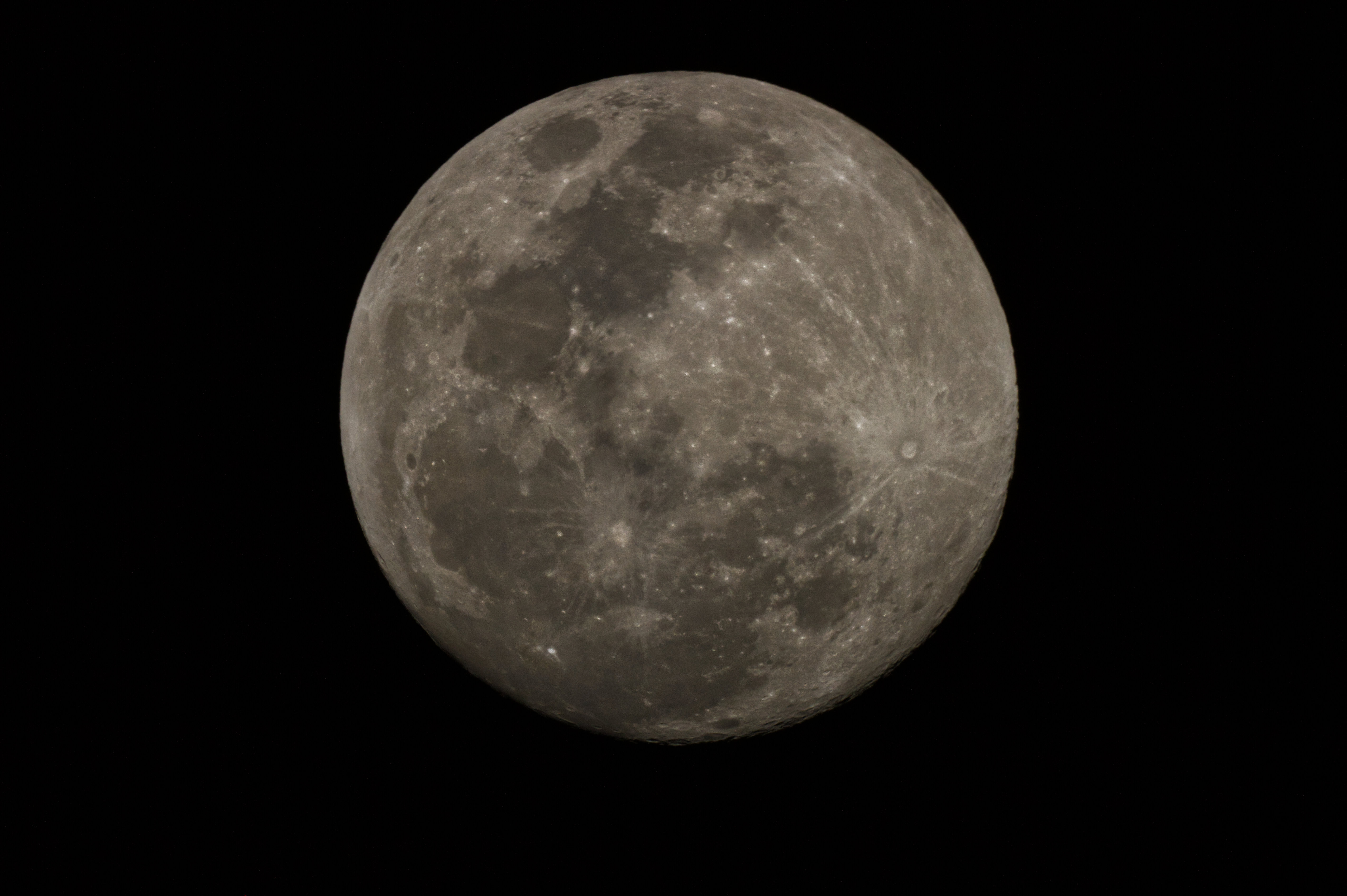
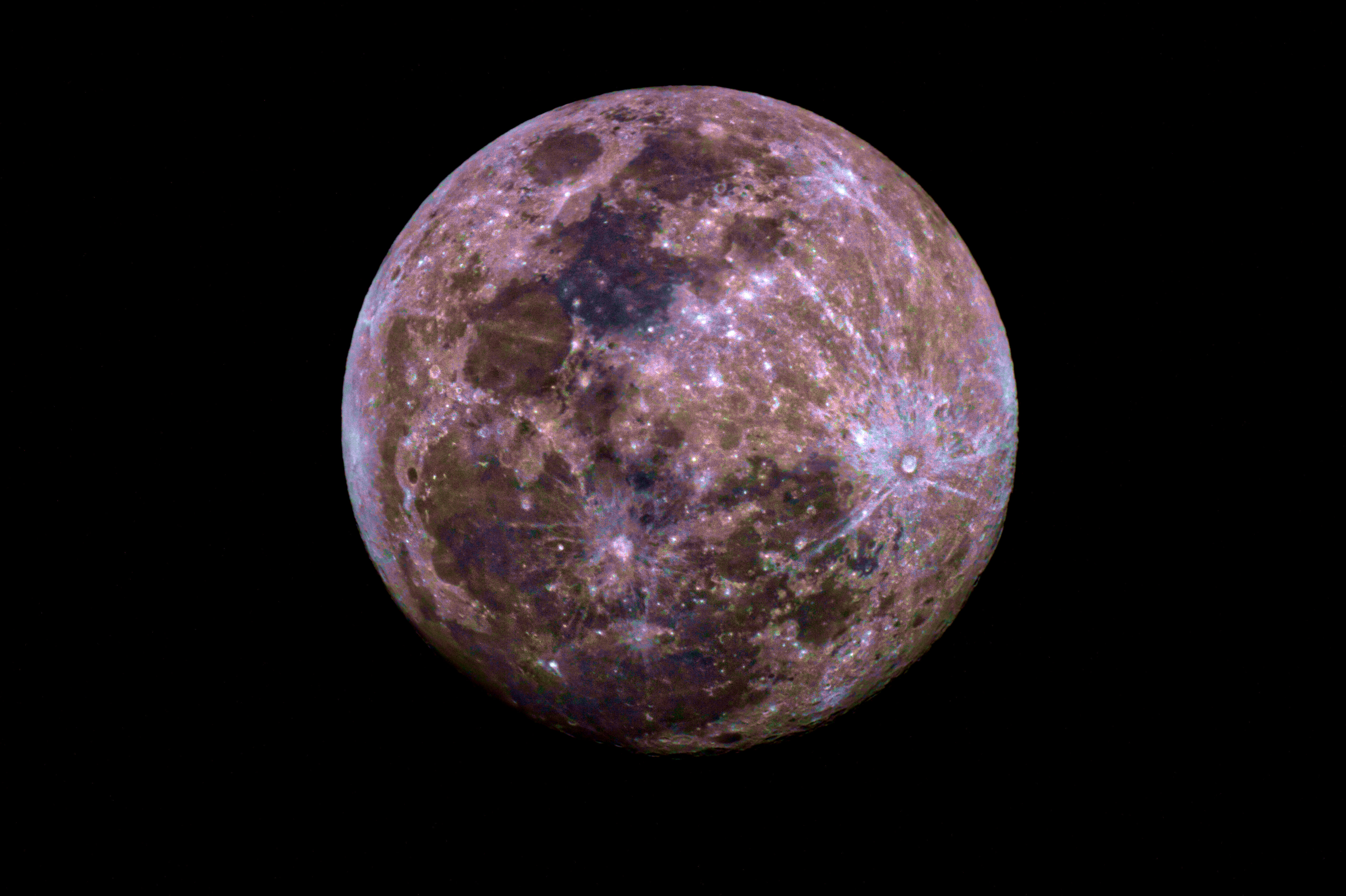
Floyd Glick (WD0CUJ) took these astronomical color images of the Moon on Friday night. He took these unfiltered images through his 5 inch Maksutov telescope (unguided). Floyd wrote: “The Moon actually has color, but because it is so bright our eyes perceive it as black and white. I have enhanced the colors (solar temperature = 5900K) in the last picture to illustrate them better.”
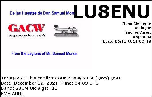
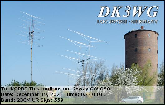
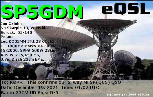
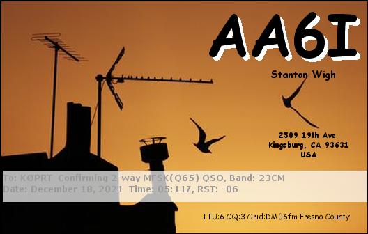
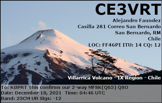
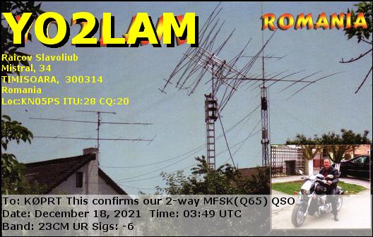
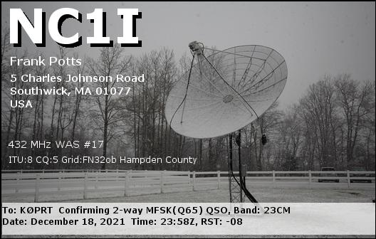
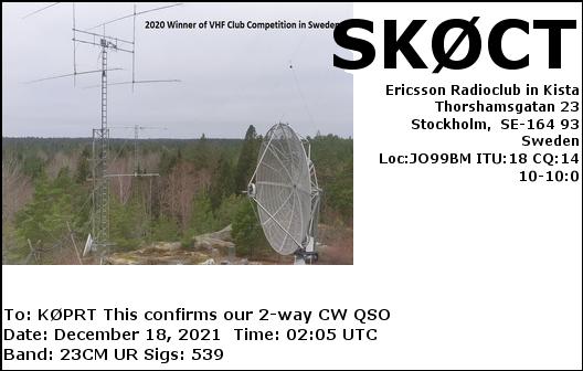
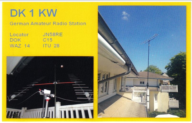
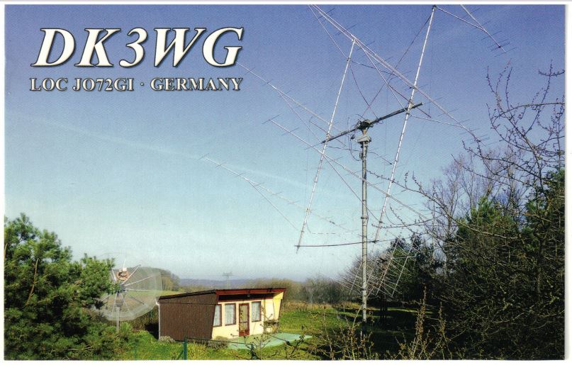
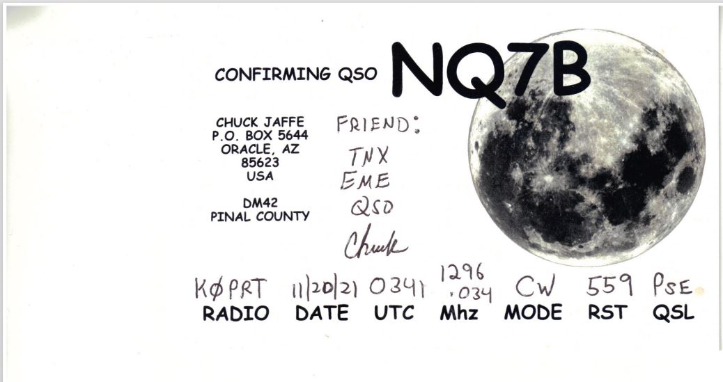
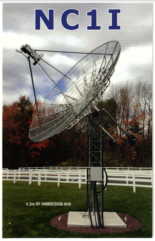
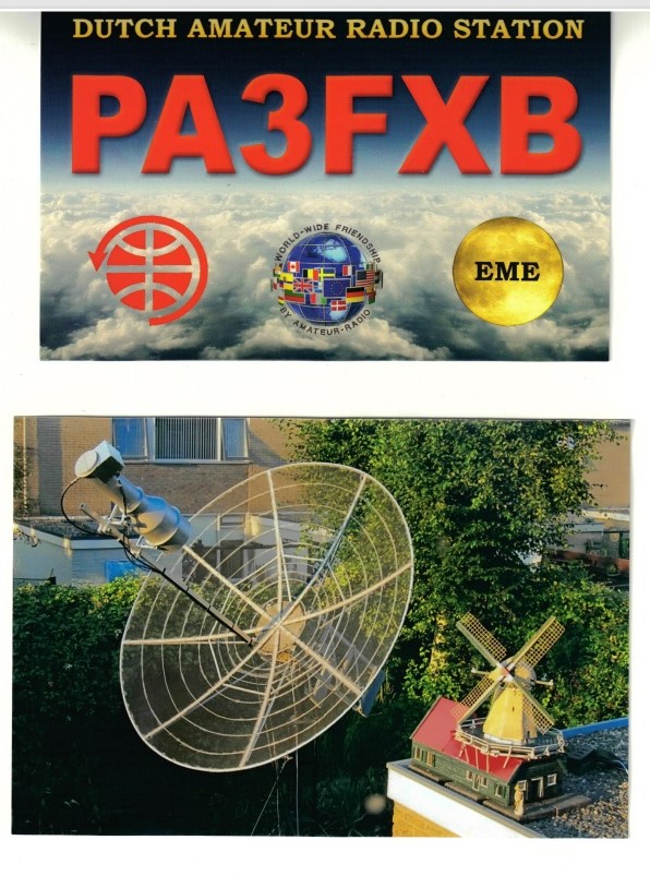
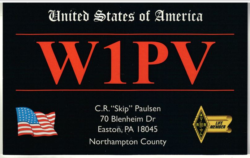
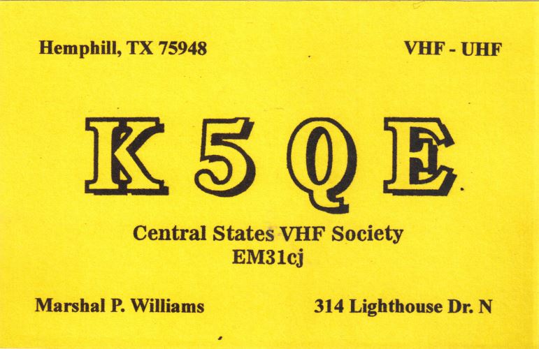
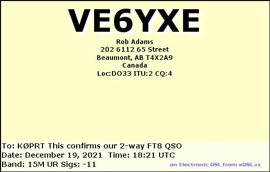
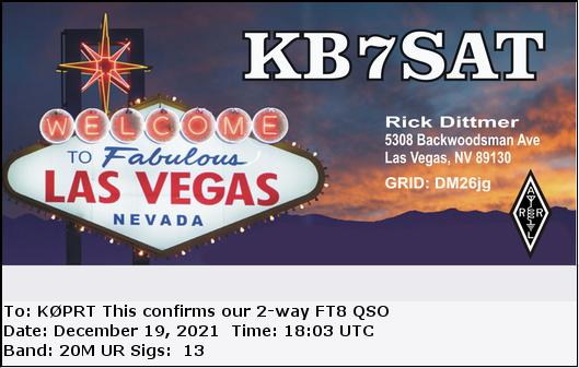
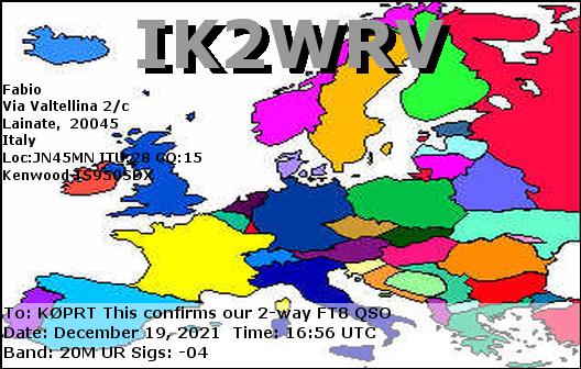
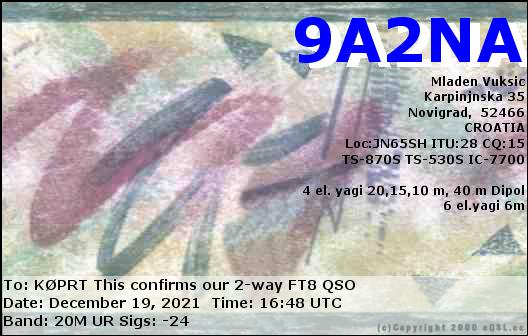
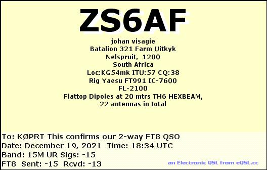
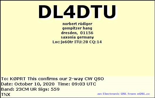
QSL confirmation cards we received for our EME contacts, by eQSL and post office mail. Countries represented are Argentina, Chile, Germany, The Netherlands, Poland, Romania, Sweden, and the United States:
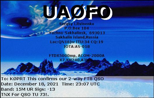
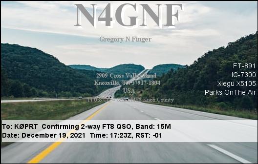
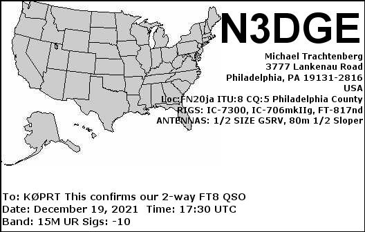
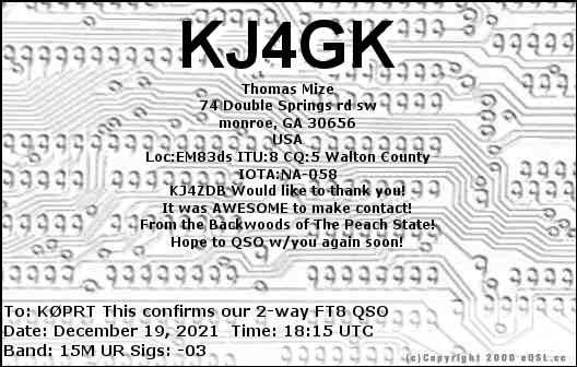
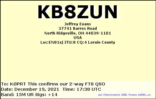
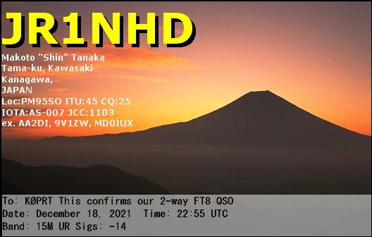
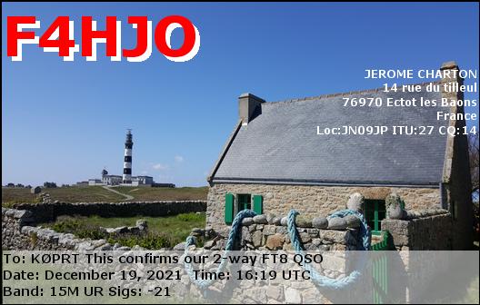
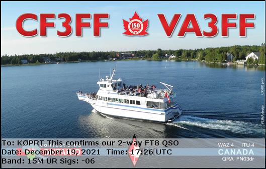
Some of the variety of QSL cards we received for our high frequency (HF) FT-8 digital contacts from Sunday morning, on the 15 and 20 meter bands. We reached North and South America, Europe, Asia, and Africa:
This past weekend our radio telescope group DSES successfully operated EME (Earth Moon Earth) Moon bounce communications again. EME Moon bounce is transmitting and directing signals to reflect off of the Moon, about 240,000 miles away in space, and communicate with anyone else on Earth who has the Moon visible above their horizon and who has similarly capable equipment. As we did last year, we participated in the ARRL annual EME contest. We used our restored 60-foot dish antenna, operating at 1296 MHz, with our call sign K0PRT. This turned out to be our smoothest and most successful EME operation to date.
We can only communicate sending signals off of the Moon when the Moon is above our horizon. For this past weekend the Moon was just past full, which means the Moon rose just after sunset, and set shortly after sunrise. That means we could only operate during the night time — all-nighter operations.
Ray Uberecken (AA0L) and Gary Agranat (WA2JQZ) were the primary team on the site operating for the full weekend. Marc Stover was on site all of Friday night, taking time-lapse night photography of the dish antenna as it tracked the Moon, with the starry sky moving as the Earth rotated. Our science lead Dan Layne (AD0CY) was on site on Saturday afternoon and evening. He particularly helped us properly configure our digital mode, and he succeeded in making Q65 digital contacts to South American and Europe. Both Marc and Dan also got some experience calling CQ on SSB voice, and they heard their voice signals traveling at the speed of light reflected back about 2 seconds later.
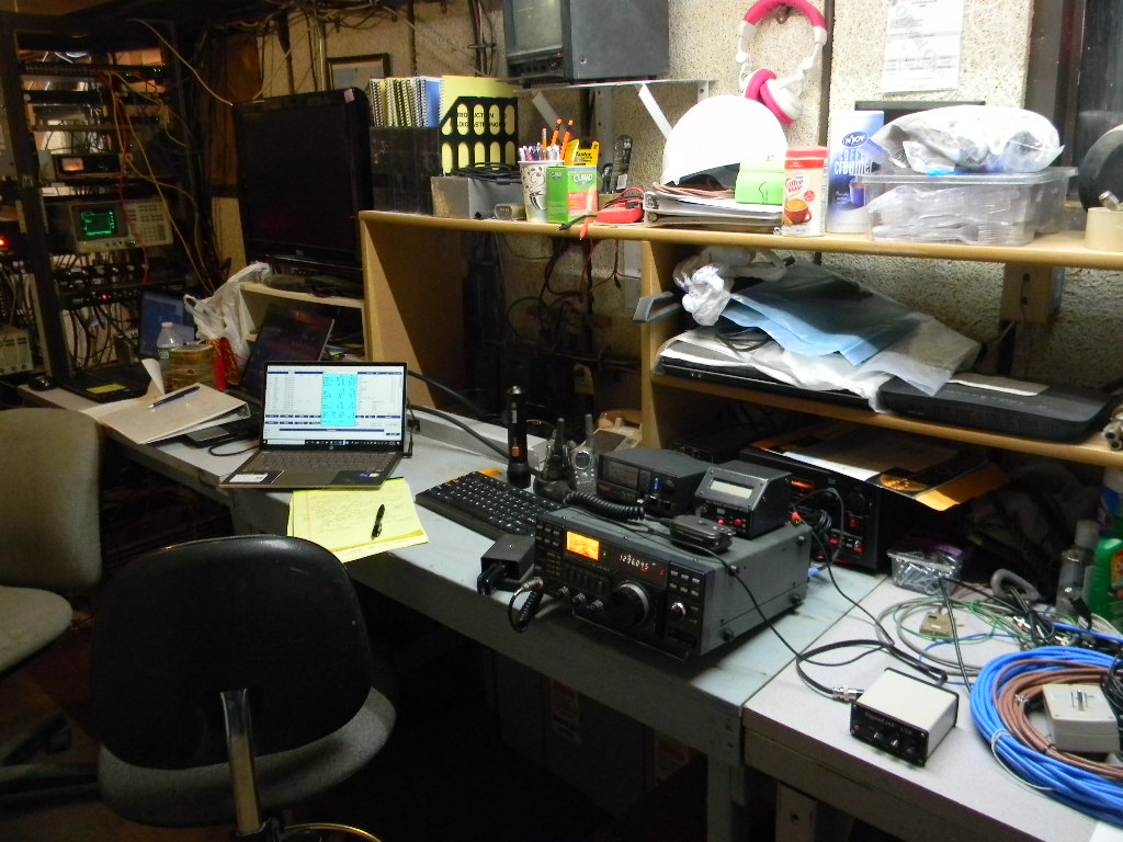
Our set up overnight Friday. We used an ICOM transceiver transmitting 150 Watts. A Morse Code keyer was attached, set to 15 words per minute (WPM). The keyer device was also able to send code by typing characters on the keyboard, but we kept to sending the standard way. This is my preference (Gary), yet this also enables flexibility to adjust one’s sending as one hears the conditions. We also used the microphone for SSB voice. On Saturday night, in addition, we tried the Q65 digital mode, using the Signalink box to the right of the transceiver, connected to a laptop. Another laptop to the left of the keyboard kept our contact log digitally. It was also set up with a WSJT 10 program, to display to us the needed Doppler shift between our transmit and receive frequencies, to correct for the difference in speed between our site and the Moon. When we transmitted, we monitored the green oscilloscope and power supply on the rack at left, to verify we in fact were sending out a signal to the antenna.
This was our most successful weekend EME Moon bounce operation to date. We made 19 contacts the first night, and 26 contacts the second. (In comparison, last year for the first weekend of the contest we made about 25 contacts, and we operated then for just one night.) Just about all of our equipment worked perfectly and smoothly. 42 of our contacts were by using Morse Code. Dan made our two Q65 digital mode contacts: to IK7EZN in Italy and CX2SC in Uruguay (our only South American contact). Our other contact was using SSB voice (with DL6SH in Germany). EME voice communications requires better equipment capability and often also more power, so making EME voice contacts is generally rarer.
Almost all of our contacts were done between Moonrise and about 1 AM local time, on each of the two nights. We had a moon path to Europe until about that time. By then Ray and I (Gary) were feeling tired enough, and the European signals were becoming sparse. We were aware that in another hour or so Japan should have moonrise and give us a communications path to us. But we decided getting some sleep was more important, and we chose to sleep. We woke again around sunrise and went back on the air, with the Moon then to the west over the Pacific Ocean. On Saturday that enabled us to work DU3T in the Philippines, and VA7MM in British Columbia, Canada. We heard DU3T work an Australian station, but we didn’t hear the Australian station ourselves. We tried calling CQ ourselves, but didn’t hear anyone else. On Sunday morning we didn’t succeed in contacting anyone — we suspected we might not find anyone by then, but we believed the try was still worth it. (By comparison, last year once the Moon gave us a path across the Pacific, we were able to work 2 stations in Japan and one in Australia.)
On our second night we made contact with our DSES member VE6BGT Skip Macaulay in Alberta, Canada.
With our 60-foot antenna we are probably one of the stronger and more capable stations on the air. We consistently got strong signal reports from other stations. I typically got RST reports of 579. Most of the stations I gave signal reports to had much lower values, from 219 to 569. We were outputting about 150 Watts.
As an indication of our good signal, on Saturday night I had a run of 18 Morse Code (CW) contacts in a row, in a period of about an hour and a half. That is, after I completed one contact, I heard someone else trying to contact me, and I then continued with them. This kept happening for 18 contacts straight. In ham radio terminology this is called a “pile up”. This is fun and uplifting when it happens. But it also takes endurance and energy and patience.
Often the signals we heard were extremely weak. And so there is definitely some skill to bring to bear. Depending on conditions, I may need to repeat key parts of the message many times. For Morse Code CW I may need to adjust the speed of my sending to a rate and pattern that I think the other person can copy. By choosing how I send, I indicate to the other person how I am hearing him or her, and that person can then adjust to my conditions too. It helps to be mindful too, so that one doesn’t make the other person feel intimidated. We are trying to make successful contacts, we also are part of a community.
Of our total 45 contacts, 28 (the majority) were with Europe. Those were with Germany (DG5CST, DL6SH, DL7UDA, DF3RU, and DL0SHF), Poland (SP6JLW, SP7DCS, SP9VFD, SP6ITF, and SP3XBO), Sweden (SK0CT, SM5DGX, SM6FHZ, SM7FWZ, and SM4IVE), Czech Republic (OK1KKD, OK1CA, OK1CS, and OK2DL), Italy (IK2DDR, IK3COJ, and IK7EZN), France (F5KUG and F6KRK), England (G4CCH and G3LTF), Finland (OH2DG), and European Russia (RA3EC). 12 contacts were with the continental US: WA9FWD (WI), N8CQ (NC), NQ7B twice (AZ), WK9P (IN), N5BF (CA), WA6PY (CA), WB8HRW (OH), W2BYP(NY), K2UYH (NJ), K3WM (PA), and W6YX (Stanford University, CA), plus one with Alaska (KL6M). 2 were with Canada: VE6BGT (AB), and VA7MM (BC). Plus we had the digital contact with Uruguay CX2SC. And DU3T in the Philippines.
***
I’ll mention, during the daylight hours on Saturday, while we had some quiet time in between Moon passes, Ray and I each spent some time with other activities. Ray did some autumn cleaning of the operations trailer. That included reorganizing the rack equipment, to make it easier for our current needs, and removing cables not in use. Ray also switched our cable for receiving GPS to an antenna on the roof, from the portable antenna we had been using inside.
Meanwhile I went to operate our HF (High Frequency) ham radio station at the bunker. I had not been on site for over a year. I wanted to check that our HF equipment and antennas were still functioning Okay. Starting around 1 PM local time I made some casual SSB contacts with our multiband vertical antenna and our directional 3-element Yagi antenna on the 50-foot tower, on the 20 and 15 meter bands. Most of those contacts were Parks on the Air stations around the country. I contacted NB6GC as well, the USS Hornet Museum ship in Alameda, CA (Bay Area) for a special event commemorating the splashdown of Apollo 12. The operator there noticed our callsign for DSES, and he told me he would be operating EME that evening too, though I think on a lower frequency. I also tried going on the 40 meter band with the vertical, but I mostly heard regular weekend nets, and I didn’t want to interfere with those. Starting at 2 PM local I then operated on the ARRL November Sweepstakes SSB contest. I chose to stay mostly on the 15 meter band with the Yagi, as 15 meters seemed more relaxed than 20 meters, and we had good propagation to the US northeast. I also swung the antenna around to contact stations I heard in California and Washington State. I sometimes searched around the band, I sometimes held a frequency and called CQ. Later I did try 20 meters too. In all I made 57 contacts, to 32 of the 84 ARRL sections in the US and Canada. Besides getting on the air and testing our equipment, I was interested to have our club station with our callsign participate with the rest of the ham community, so that other hams get to know us and to feel us as part of their community. I operated on HF for about 2 hours, though not all at once.
The one maintenance issue I had for the HF station is that the Yagi antenna direction was offset from the indication on the rotator control by about 80 degrees. I compensated for this while I operated. I remember that when we last had the tower lowered for maintenance over a year ago, the rotator didn’t seem able to lock.
***
As I mentioned, this was our most successful EME event to date, with 45 contacts and with no major equipment problems to troubleshoot. The automatic tracking system worked flawlessly, allowing us to concentrate on the signals we heard and making contacts.
This past weekend’s operation was the first of two parts of the ARRL EME contest in which one can use 1296 MHz. We plan to operate for the second part too, which will be on the weekend of December 18 & 19, 2021. Several more of our members, and at least one local ham, plan to come for that.
***
EME has been a major strategic goal of DSES since we started restoration of our 60-foot antenna in 2009. An immense amount of work was done in our group to achieve the capability we have now. The most visible aspect now is in making the operation work, and in developing our experiences to make the operation work well. Yet behind the scenes there have been many people, and much work in many more aspects — for example, the infrastructure repair and modernizing, restoring full electric power, developing from scratch the automatic tracking, to name just a few. To my mind this is a lot like having our own Moon mission.
And at the same time we’ve been developing our science capability and doing science too.
To me as well, hearing one’s signal come back 2 seconds later at the speed of light from the Moon and communicating with others around the world this way still takes my breath away. I really am doing something physical with the Moon, a celestial object out there in space, and the Moon physically responds back. To me the Moon is no longer something in the sky I just see, it is a physical object in space I have touched in some way and it has responded. And the speed of light and the wave-nature of light are no longer something just theoretical — I have to deal with those practically. I think something has changed and grown, for each one of us in DSES who have had the opportunity to work with EME.
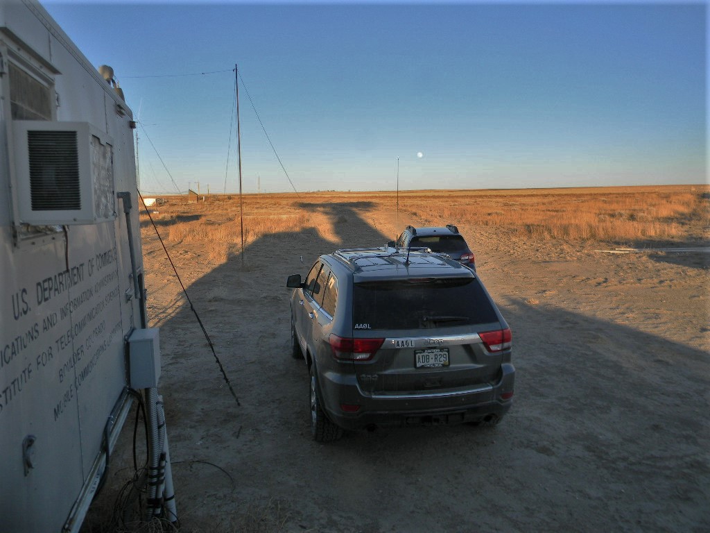
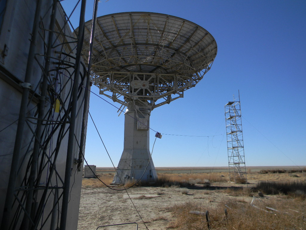
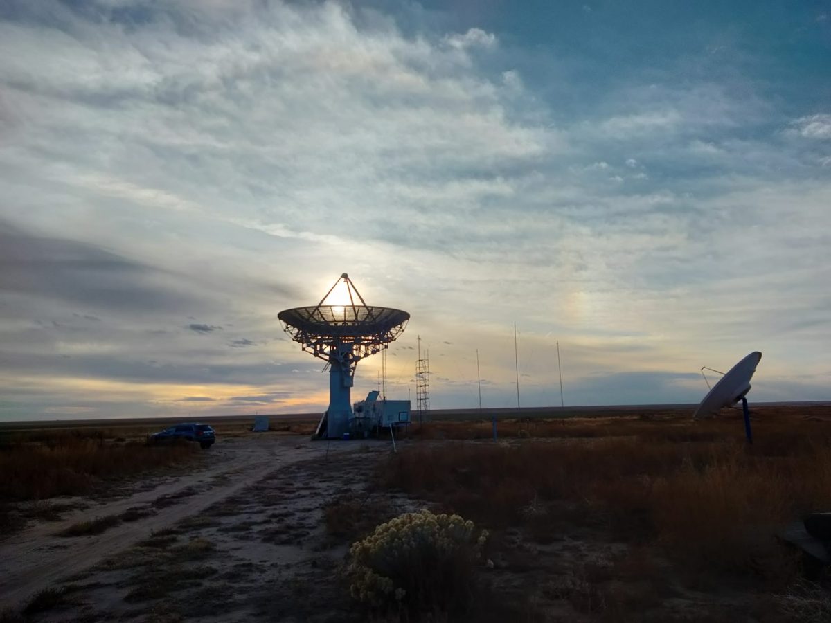
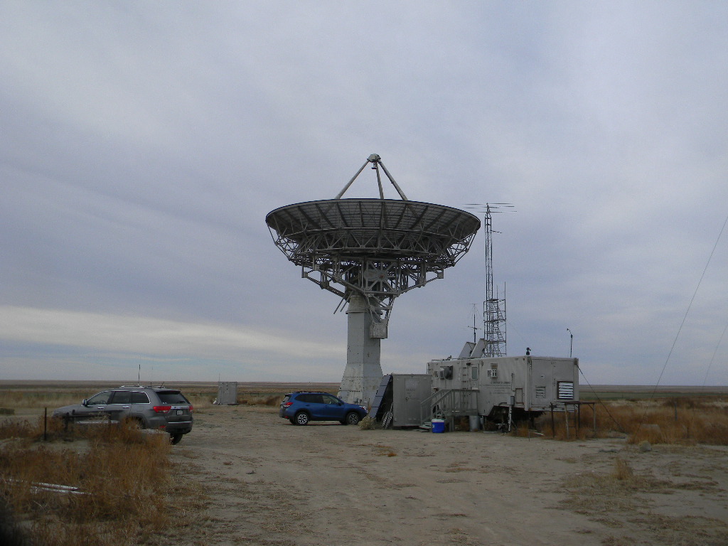
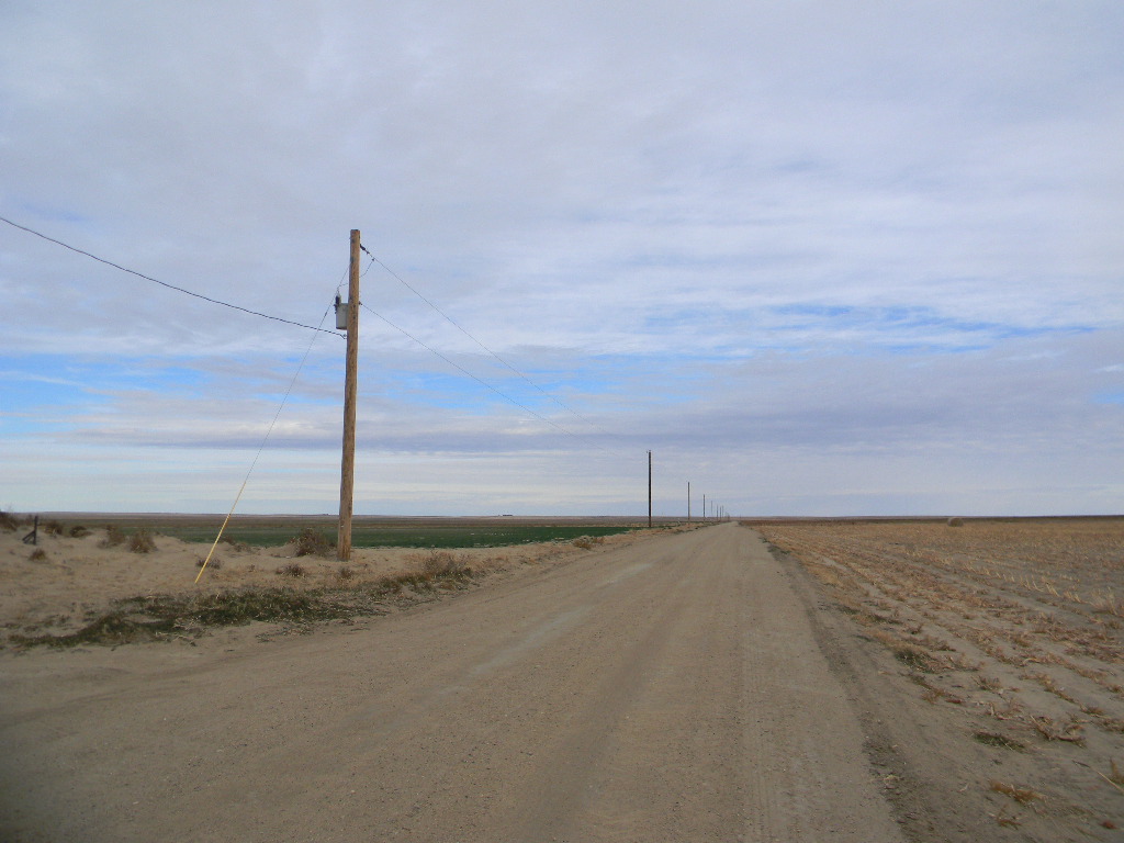
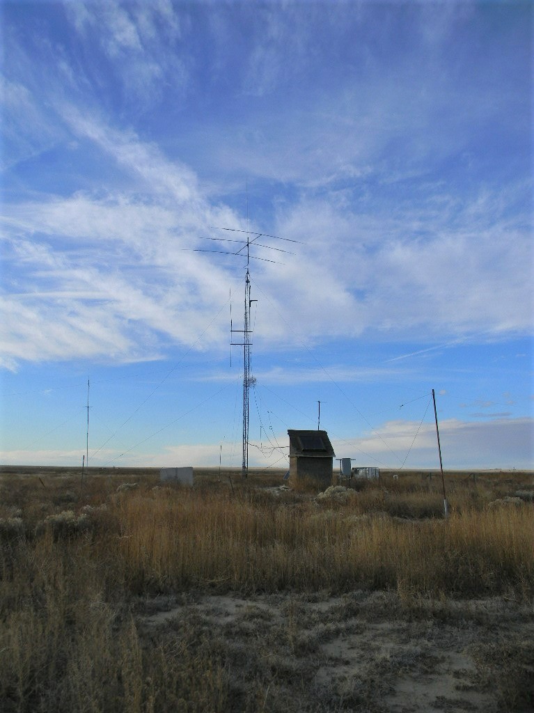
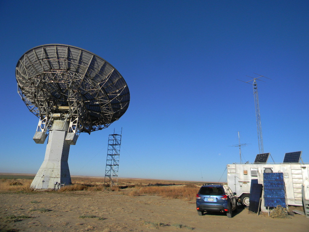
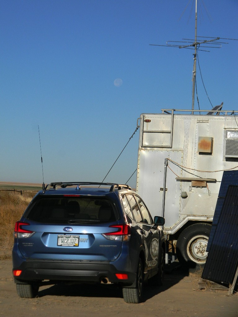
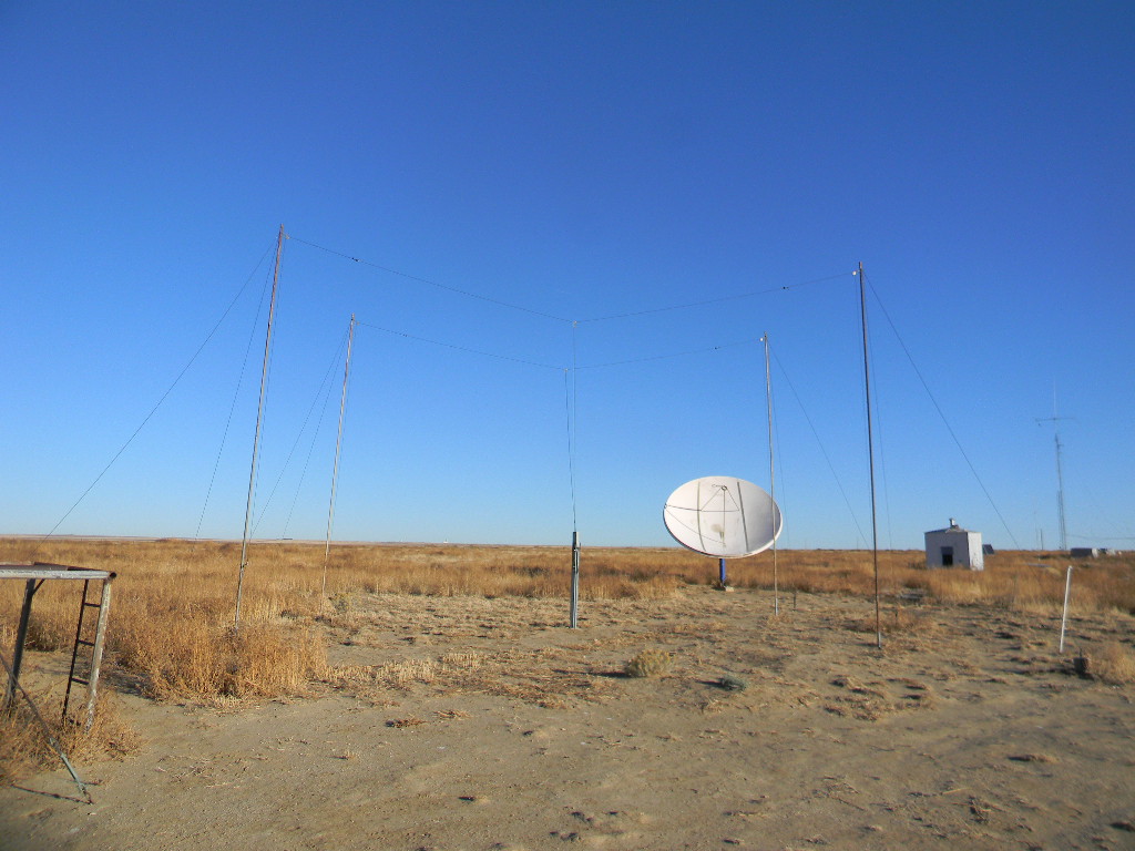
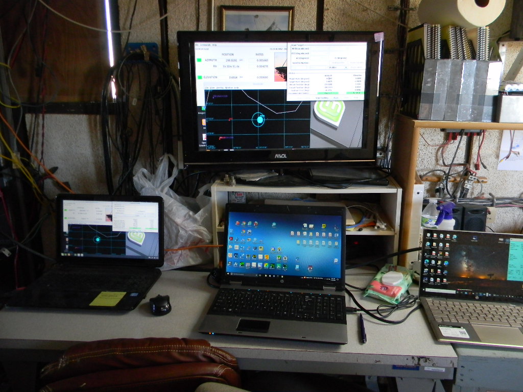
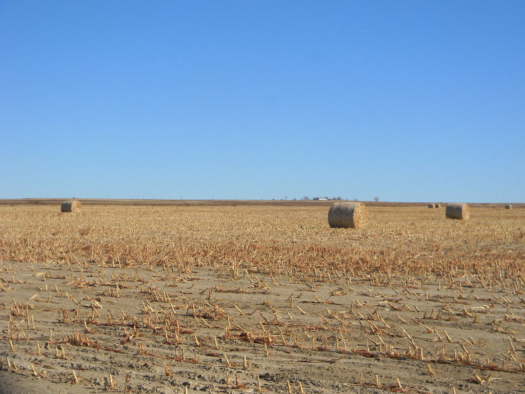
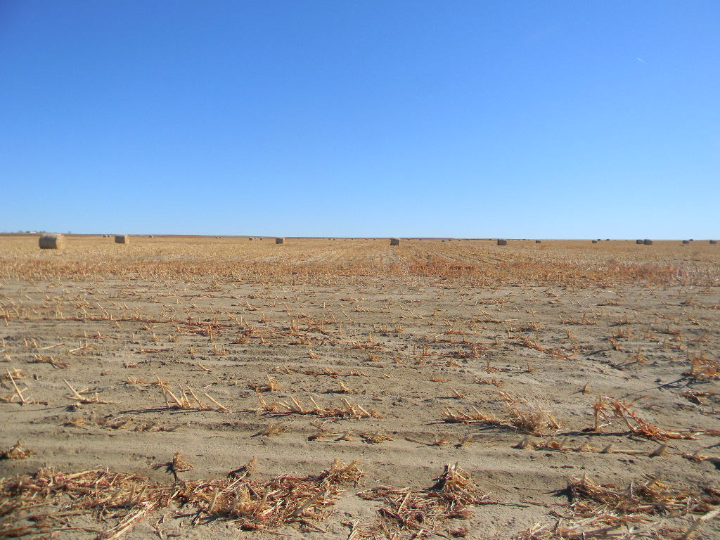
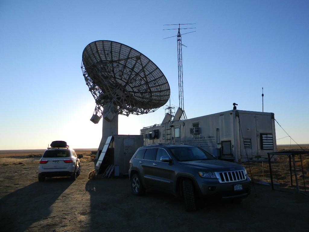
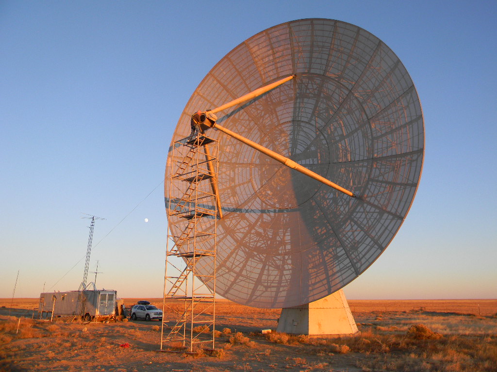
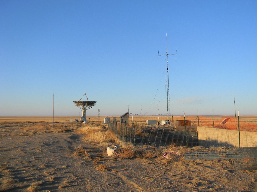
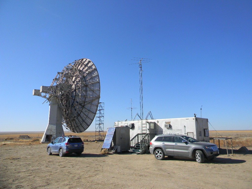
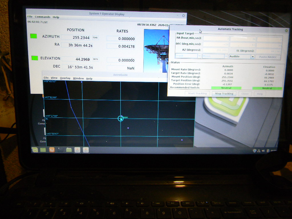
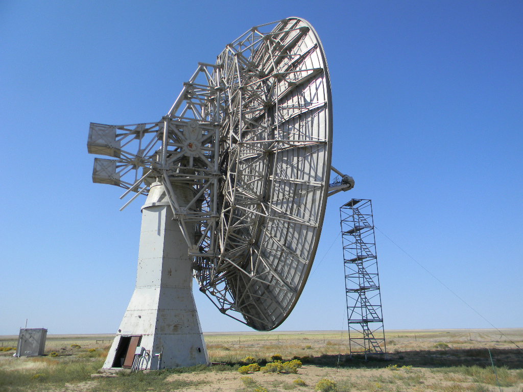
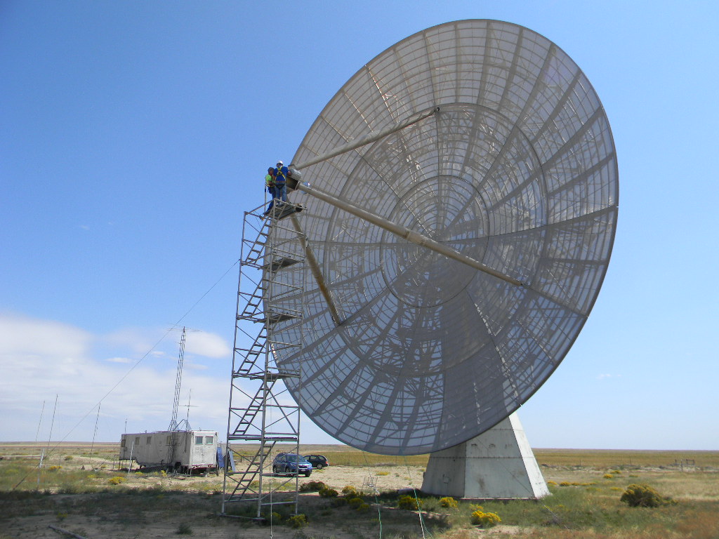
Our 60-foot dish antenna in stowed position and the operations trailer, during the daytime break Saturday, before the Moon rose again after sunset. The antenna focus has installed a 1296 MHz dual polarized feed.The power lines on Delores Lane that provide our site with electricity. Our high frequency (HF) ham radio antennas on the site. On Saturday afternoon while we waited for the Moon to rise again, I operated for a couple of hours for an ARRL HF contest: the November SSB Sweepstakes. I used the directional Yagi antenna on the tower and a multi-band vertical antenna at left. For the Sweepstakes contest I made 57 contacts around the continental US and Canada, plus with Hawaii and Puerto Rico. Before that I also made some casual contacts, mostly with hams who set up at parks in various parts of the country.After about 1 AM each night we took a break and got some sleep. When we woke a few hours later, the Moon was still above the horizon and we operated Moon bounce for a little while longer. On Saturday morning that gave us contacts with DU3T in the Philippines and VA7MM in British Columbia, Canada. This photo is on Sunday morning as we repointed the antenna to the Moon, near the horizon above my car. On Sunday morning we made no further contacts, but if anyone else was there on the air we would have heard them.The two wire antennas in the foreground are phased dipoles, which we use for receiving natural signals from Jupiter and its moon Io, caused by Io moving through Jupiter’s strong magnetic field. The 12-foot dish antenna is a new project that will be part of a radio astronomy interferometer we are developing.Closer view of one of our dishes we will use for radio astronomy interferometry.Our operating station early Sunday morning. We had coffee and muffins ready.You can see the antenna tracking software displays. The Moon is shown on an astronomical sky map. The circle around the Moon represents the beam width of our signal. Other windows on the display indicate the coordinates the antenna is pointing to, its motion, and settings for how we are controlling it. On my laptop on the far right, I have a logging program (not shown) and a program that shows me the position of the Moon (in Az & El and RA & Declination), and the Doppler shift corrections we need to continually make as our relative motion between our location and the Moon changes.The ICOM transceiver we were using, tuned to 1296 MHz, and the Morse Code keyer for sending code. We had the keyer set for 15 words per minute. I wrote down (copied) the code that I heard on the paper pad. I save the hard-copy record, in case I need to double check a call sign or a contact detail for the contest or QSL request.The farm and ranch fields across the road from our site.
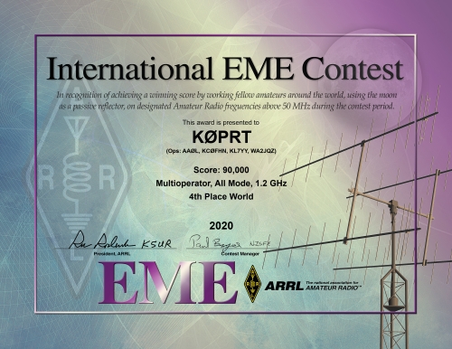
DSES participated in the ARRL Earth-Moon-Earth (EME) moon bounce contest last autumn. The contest was spread over 3 weekends. We participated in the weekend segments of October 10-11 and November 28-29. The ARRL has now posted the contest results.
We operated solely the 23 cm (1296 MHz band) with our 60-foot dish antenna. We used CW Morse Code and SSB Phone on the first weekend, and CW and Digital JT65 on the second weekend. We made 50 contacts over the two weekends. However, for contest scoring, stations we contact again over both weekends only count once. Therefore for scoring, we were credited with 36 contacts. Our team consisted of several operators: AA0L, KL7YY, WA2JQZ, and KC0HPN. Glen Davis also was crucial for adjusting our antenna pointing system and ensuring we were operational. (WD0CUJ and Michael Namieka also came out, and made a moon bounce test transmission, but didn’t make contest contacts.) And so we submitted our contest log in the All Mode, Multioperator, 1.2 GHz category, with our call sign K0PRT. Worldwide we came in 4th place in this category.
In addition, we were contacted last month by Rick Rosen, K1DS. He wrote an article for QST about the 2020 ARRL EME contest, and he included dedicated segment of the article just for DSES. The article is here: 2020 EME Contest – Final Results – Version 1.1 (arrl.org)
On the weekend following this past Thanksgiving we participated in the second round of the ARRL EME Contest, which ran for 48 hours, on November 28 & 29, 2020, GMT hours. This time it was a cliff-hanger in that we almost didn’t get on the air. But with some dedicated effort we succeeded again. This time we contacted some new places. And we added JT65C digital mode.
Team members for this operation were Ray Uberecken AA0L, Gary Agranat WA2JQZ, Myron Babcock KL7YY, and Bill Miller KC0FHN. Floyd Glick WD0CUJ came out also for one evening, accompanied by our new member Michael Nameika.
For this weekend the Moon was at almost full phase. That meant that it would be up mostly during our nighttime, which therefore was when we would have to do our operations. The contest would start at 0000 Hours GMT, which for us was 5 PM on Friday evening November 27. The Moon was already rising at 3:19 PM, so it would be up high enough to begin operating right away, once the contest started.
The Moon above our horizon already at about 4 PM Friday.
Ray and Bill arrived Friday afternoon by 3 PM to set up and do last minute testing. I (Gary) arrived soon after.
In our testing, we found we could receive the 1296 MHz beacon Ray set up at his home in Peyton. But we couldn’t properly transmit.
We quickly slew the antenna to the service tower, and Ray retrieved the amplifier at the feed. The thinking was the problem might be there.
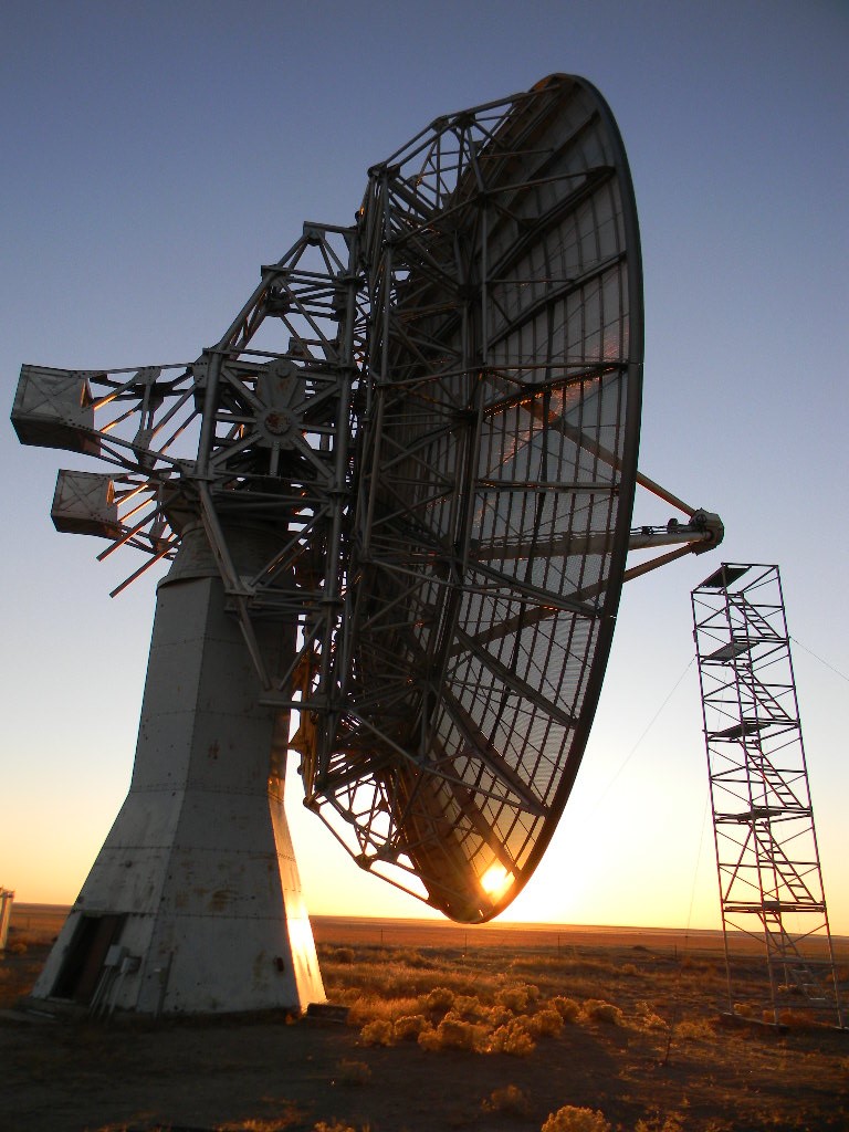
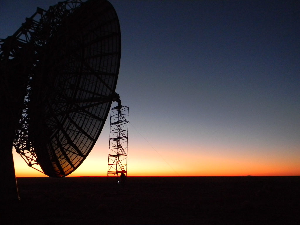
The 60 foot dish antenna lowered to the service tower, as the sun set.Ray climbed the service tower and retrieved the amplifier at the feed.Ray retrieving the amplifier.
Ray did some quick testing of the amplifier. But an initial check didn’t find anything wrong.
Ray quickly tested the amplifier in the operations trailer, but didn’t find a problem. Outside, the Moon was rising, and the contest was starting. But were were not operational.
Ray then climbed back up the tower to return the amplifier to the feed point. We thought about what else could be wrong.
We then checked how much power was being drawn by the amplifier in the pedestal. The power meter was reading about 30 Watts when we tried to transmit, when it should have been reading about 200 Watts. At that point the sky was getting dark. It would not have been safe to do any more climbing. And so for the first night of the contest we couldn’t operate.
Bill returned home, but was available the next day for coordination in Colorado Springs. Ray and I spent overnight at the site, to continue troubleshooting on Saturday. We would have the whole day in sunlight, until the Moon rose for the second pass at 3:47 PM.
Ray replacing the amplifier at the feed, as the sun set.
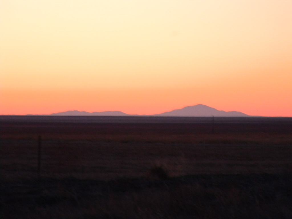
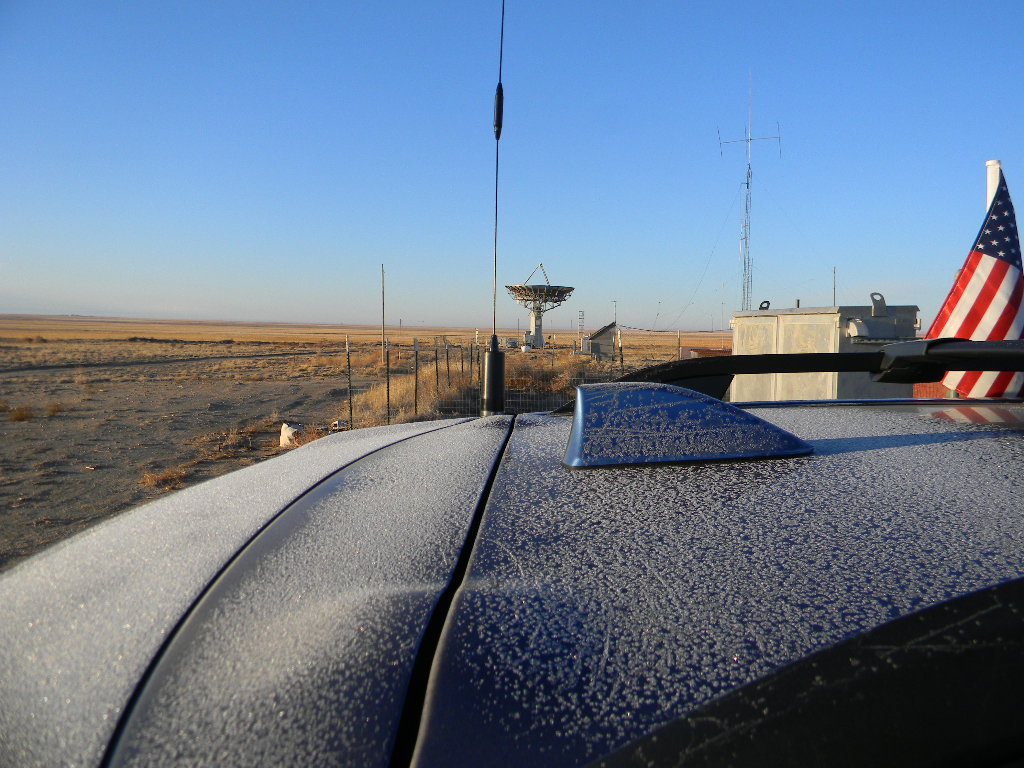
Pikes Peak was visible on the northwest horizon, as the sun set.The frost on Gary’s car the next morning.The bunker Saturday morning.
Before going to sleep I (Gary) made some HF ham radio contacts. So we got on the air still, but on HF. This weekend there was also another contest, the CQ World Wide CW (Morse Code) Contest. On 160 and 80 meters I made three contacts with Canadian stations. There were lots of US stations on, but for the rules of this contest, you have to contact stations outside of your country (or more precisely outside of your DX area, which for us is the CONUS). I afterwards made some HF FT8 digital contacts for the club, on 80 and 40 meters. On 40 meters we made our first DX contact with New Caledonia in the southwest Pacific, with station FK8HM. This was with our recently repaired vertical antenna, so this showed our vertical was working OK.
Early the next morning I made some more CW contacts for the contest, this time on 40 meters using the vertical, and on 15 meters, using both the vertical and Yagi antennas. On 40 meters, while it was still dark across the Pacific, stations in China, Hong Kong, and South Korea were heard, but I didn’t succeed in making contacts. I did succeed though in contacting two Japanese stations. Then on 15 meters, with daylight across the Atlantic, the band was wide open to Europe. For a few minutes while on the air, we made contacts with France, Spain, and Slovenia, and also one contact to the south with Brazil.
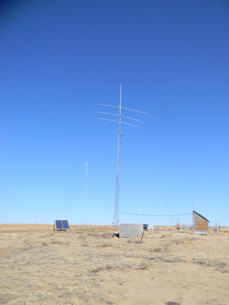
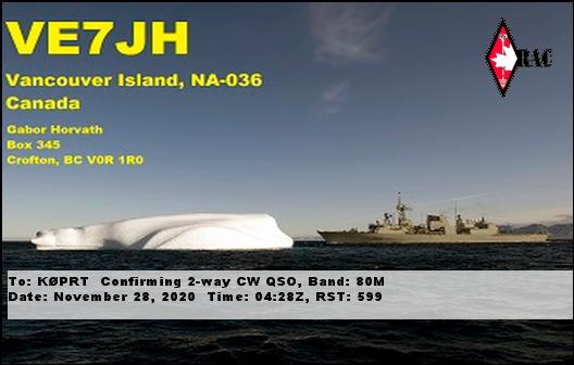
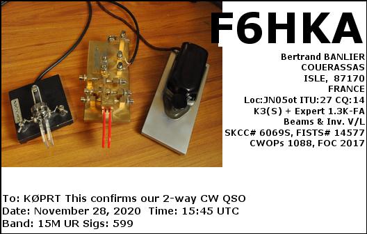
Earlier during the year, the 3-band Yagi antenna bank angle slightly tilted. The 5-band vertical antenna also was damaged, probably both from storms. Earlier in the fall we repaired a bent piece of the vertical antenna, and reconnected the radial wires that had been severed. The HF operating showed these were at least working OK again. The 160 and 80 meter contacts were made with dedicated diploe antennas, also lightly visible in the picture. The Yagi antenna on the tower is aimed towards the northeast, towards Europe.This is an eQSL confirmation we received from VE7JH in British Columbia, Canada, for our 80 meter Morse Code (CW) contact on Friday night. The card came with this caption information: 08 Aug 2009 Frobisher Bay, Baffin Island HMCS Toronto navigates an iceberg HMCS Toronto navigates past an iceberg near Frobisher Bay off the coast of Baffin Island while conducting sovereignty patrols as part of Operation NANOOK 09. Operation NANOOK 09 is a Canada Command sovereignty operation conducted with the participation of personnel, ships and aircraft from the Navy, Army and Air Force, working under the command of Joint Task Force (North) (JTFN). The operation runs from 06 to 28 August 2009, in Canada’s eastern Arctic. Photo by: Corporal Dany Veillette, Canadian Forces Joint Imagery Centre, Ottawa, Ontario. An eQSL confirmation we received from F6HKA in France, for a Morse Code (CW contact) Saturday morning on the 15 meter band. His card shows several Morse Code keys.
Ray and I had breakfast and resumed troubleshooting work at 9 AM. We retrieved the amplifier again, and this time did a much more thorough test. Ray found one diode was leaking current. But this was a circuit safety issue and not a showstopper for transmitting. Ray replaced the diode, and returned the amplifier to the feed.
Ray retrieved the amplifier again Saturday morning.Ray doing a thorough test of the amplifier. Nominally it should boost our signal to about 200 Watts at the feed.Ray tested the output of the amplifier by sending the signal through the disc cone antenna on top of the operations trailer.
We then considered what else could cause our problem. Ray tested the conductivity of our feed lines. We have two coax cables running from the operations trailer to the feed. Ray climbed to the feed, and connected the two cables there. Then we measured the conductivity going out and coming back, together at the same time. His software analyzer showed Coax cable #1 had a fault at 135 feet down the line, and Coax cable #2 had a fault 185 feet down the line. This corresponded with where there are swivel joints for the cables, where the fixed pedestal interfaces with the moving dish antenna structure. A signal test also showed there was more loss on the lines then expected.
The oscilloscope showed we didn’t have as strong as signal as we expected along the feed lines.
At first Ray wondered that the swivel joints might be the problem. However, on visual inspection those were seen to be OK. The problem was eventually traced instead to the weight of the cables at that location pulling on the centers of the feeds, causing those to slip out.
Ray was able to repair Feed Line #1. We then did more testing, with Ray’s beacon and the W0TTT beacon in Como, CO, and with an SSB tropospheric scatter contact with Myron in the Springs, and found we were working well. We were back in business.
Saturday, troubleshooting. The disc cone antenna is on the short tower on the left side of the trailer.
Myron drove out to the site, and operated with us the second night. While Myron was on his way, I slew the antenna for Moonrise, getting more practice with the System 1 automatic tracking.
As soon as the Moon rose we heard CW and digital signals. We again had to figure out the Doppler shift correction, using the WSJT 10 software. At the start we made several CW contacts with Europe: to Germany, England, Croatia, France, Poland, and Austria.
Eventually we also tried digital JT65C –for the first time. That was a learning curve, but we finally got it. One of the tricks for that was that the waterfall window on the JT65C has a bar at top designating where the sync pulse of the signal has to be, in order for the software to decode it. Another challenge was that operators were heard with JT65 weren’t using a consistent contact exchange format. And so I had to manually edit the exchange fields quickly, in the 10 seconds between decoding and transmitting.
We made 19 contacts altogether. 16 were with CW (Morse Code) and 3 were digital JT65C. Myron tried several times to make SSB contacts. But there were no takers to respond back to us.
Over the night, I generally made the CW and digital contacts, while Ray operated the radio, including keeping up with the Doppler shift offsets. I offered to let others make contacts too. But we were comfortable doing it this way.
Floyd came during the evening with his astronomy student Michael Namieka. Floyd showed Michael around the site, and I believe also made some HF contacts in the bunker. They watched our EME operation. They got into a good technical discussion about the component causes of the Doppler shifts. Myron had Michael send a voice CQ and test moon bounce signal, and Michael heard his voice come back about 2 seconds later.
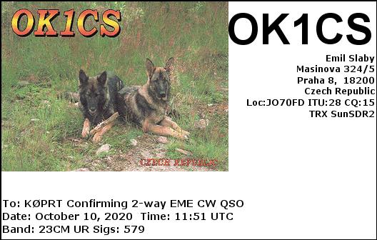
Our CW contacts included our DSES member Skip, VE6BGT — he said we sounded much stronger this time. And we found several other stations we had contacted last month too.
On JT65 we had QSOs with AL Katz K2UYH, W6YX Stanford University, and AA4MD in Florida (who last month we got on CW).
New countries to Europe this time were France and Croatia. We got KL6M in Alaska, who built our feed. We got one Japanese contact JH1KRC, who we contacted last month. And this time we had one contact with Australia, VK5MC, probably our contact furthest away from us. I am happy to report we had pileups on us. At least some of our contacts already knew something about us and our capability.
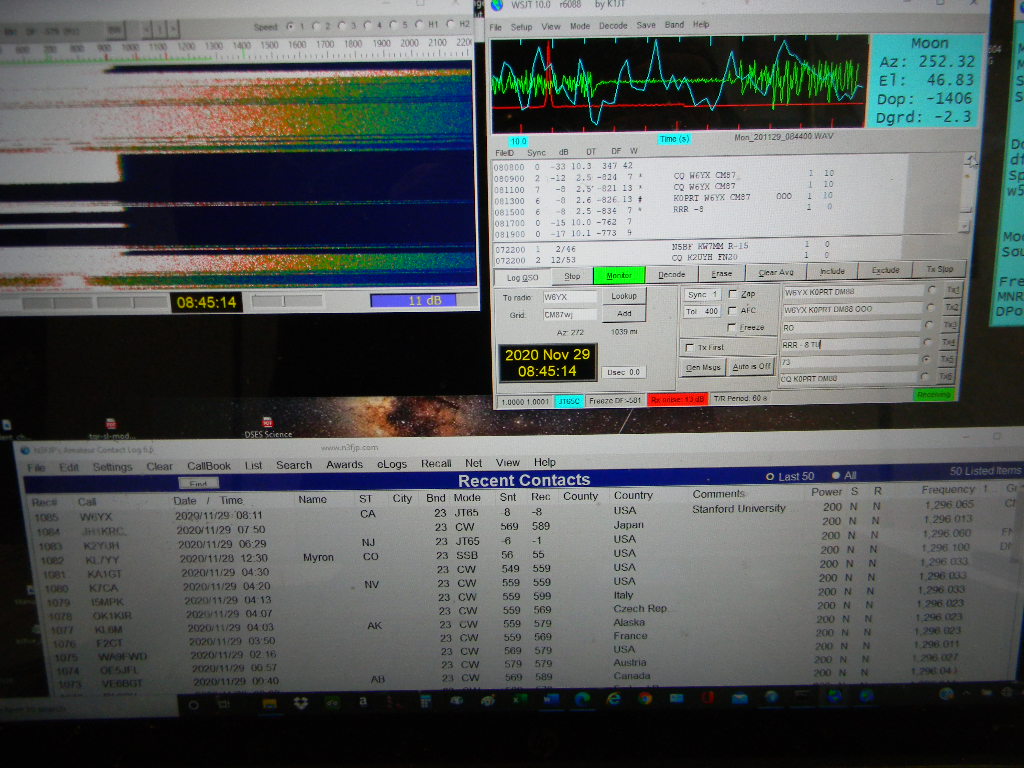
This is a record of our contacts, from the Cabrillo formatted file we submitted to the ARRL for the contest. CW is Morse Code. DG is JT65C digital. 1.2 G is the 1.2 GHz frequency band. You see the date and times in GMT, our station with the signal report we sent, and the station we contacted with their signal report to us. QSO: 1.2G CW 2020-11-28 2312 K0PRT 599 DG5CST 599 Germany QSO: 1.2G CW 2020-11-28 2317 K0PRT 559 SP7DCS 589 Poland QSO: 1.2G CW 2020-11-28 2324 K0PRT 559 G4CCH 599 England QSO: 1.2G CW 2020-11-29 0007 K0PRT 559 9A5AA 579 Croatia QSO: 1.2G CW 2020-11-29 0020 K0PRT 569 DL6SH 579 Germany QSO: 1.2G CW 2020-11-29 0040 K0PRT 569 VE6BGT 589 Canada QSO: 1.2G CW 2020-11-29 0057 K0PRT 579 OE5JFL 579 Austria QSO: 1.2G CW 2020-11-29 0216 K0PRT 569 WA9FWD 579 Wisconsin, USA QSO: 1.2G CW 2020-11-29 0350 K0PRT 559 F2CT 569 France QSO: 1.2G CW 2020-11-29 0403 K0PRT 559 KL6M 579 Anchorage, Alaska, USA QSO: 1.2G CW 2020-11-29 0407 K0PRT 559 OK1KIR 569 Czech Republic QSO: 1.2G CW 2020-11-29 0413 K0PRT 559 I5MPK 599 Italy QSO: 1.2G CW 2020-11-29 0420 K0PRT 559 K7CA 559 Nevada, USA QSO: 1.2G CW 2020-11-29 0430 K0PRT 549 KA1GT 559 Maine, USA QSO: 1.2G DG 2020-11-29 0629 K0PRT -06 K2UYH -01 New Jersey, USA QSO: 1.2G CW 2020-11-29 0750 K0PRT 569 JH1KRC 589 Japan QSO: 1.2G DG 2020-11-29 0811 K0PRT -08 W6YX -08 California, USA QSO: 1.2G CW 2020-11-29 0920 K0PRT 439 VK5MC 449 Australia QSO: 1.2G CW 2020-11-29 0946 K0PRT 599 N4PZ 599 Chicago, Illinois, USA QSO: 1.2G DG 2020-11-29 1006 K0PRT -09 AA4MD -07 Florida, USA
The automatic tracking system display, showing us tracking the Moon.The WSJT JT65 display on my computer. The upper left shows a spectrum waterfall, where we had to position the signal for the software to decode. We also at times had to adjust the audio gain, to not overwhelm the display. The upper right shows the message exchange, in this case with W6YX in California. The lower window is our logbook.
We decided to stop operating at around 3:30 AM Sunday morning. We were hearing much fewer new contacts. But also the outside wind was picking up immensely. Forecasts for the region were for gusts up to 50 knots. We stowed the antenna back to the safe position. Ray, Myron and I then got sleep in the operations trailer. Outside the temperature dropped to the low 20s, but we kept warm inside with the heaters. Myron left early in the morning. Ray and I closed the site by 11 AM Sunday, and headed back to the Springs.
* * *
Some technical feedback: System 1 was working almost perfectly. The one glitch again was that there was a discontinuity in elevation reading on Friday night as the elevation was brought close to zero (seen by Bill). I didn’t experience that on Saturday or Sunday. Otherwise, the System 1 is an immense help. It makes the slewing and tracking easy and seamless.
We had a learning curve figuring out all of the nuances and details (or the sufficient and necessary details) for running JT65. We did eventually get JT65 working well. You do need to pay attention to its peculiarities. It probably could use some guidance documents, like we have for System 1.
I will note I did try to make a number of contacts but didn’t get responses. I don’t know why that was. I am suspecting part of the reason might be due to not getting the Doppler shift offsets quite right at times. But we did get a number of good signal reports and explicit comments that we had good signals.
Later I did some research. One of our contacts KA1GT has some articles on the Doppler shift math and corrections. These might be helpful:
It was a somewhat intense weekend for the team — with not being able to operate Friday evening as it got dark, with the troubleshooting, the cold and windy weather conditions and staying overnight (for some for 2 nights) on site. But we were very pleased we got our Moon communications back. We had lots of good signal reports. We apparently were doing better than in October with our signals. We probably had fewer contacts than last time as we were spending time figuring out the JT65 and Signallink. And I suspect there might have been fewer hams on for the second night. But I think also we didn’t want to knock ourselves out, especially with all the work we did. We found a good balance that worked.
I think all of us involved were very pleased with what we accomplished this weekend. We spent the effort to troubleshoot, we got ourselves back on the air, and we made a successful second EME Moon bounce operation.
2020-11-23 DSES Science Meeting Notes, by Bill Miller
We had 16 participants in the virtual science meeting today: Thanks everyone for joining.
Participants: Dr. Rich Russel, Ray Uberecken, Lewis Putman, Bob Haggart, Don Latham, Floyd Glick, Gary Agranat, Glenn Davis, Jay Wilson, Jon Ayers, Lauren Libby, Myron Babcock, Robert Sayers, Ted Cline. Jerry Espada, Bill Miller
Agenda and notes;
Also see the Zoom Video Recording for more detail:
Myron’s Treasure’s Report Checking $1774.28. Savings $5742.15. We have 49 paid members.
Science Fair:
Bill spoke with Carol Bach the coordinator, she replied, “The Pikes Peak Regional Science and Engineering Fair will be held virtually on February 20, 2021. We are hoping that the Deep Space Exploration Society will again sponsor a special award or awards at the fair. In addition, we are hoping you or another member of your group will consider being a special awards judge. We will send you a code to unlock a showcase with digital displays that you can view. Virtual judging will take place between February 18-20, 2021.”
Bill to send board DSES Special awards criteria for approval.
“Please respond by December 2, 2020 to this email and confirm that your organization is planning to participate. Also, please let us know the name and contact email for future communications.”
Planet Walk:
Bill will write an endorsement letter and have the DSES Board modify and approve for Planet Walk Colorado Springs. See https://www.planetwalkcs.org/
Arecibo Failure:
See Bob Haggard’s repost on the Arecibo Radio Telescope status.
Problem with the 1296 feed last trip. Took down the Feed amplifier and found that the unit was stuck in the transmit configuration again due to a failed FET in the Relay driver. Fixed this and added more gate protection circuitry to solve the problem.
Also had a bad diode and a bad cable that had to be corrected.
The FT-736R Keyer connection failed on last trip but Ray fixed it.
Tried CW EME but couldn’t hear the echo.
Did receive Rays Home Based beacon bounced off Pikes Peak and verified pointing so the receiver chain is working.
Gary Underground K0PRT bunker station summary report.
FT8, PSK Reporter website showed our station was received on 40 meters during afternoon in CA and TX.
15M operation was hot
Our rare grid square (DM88) attracted many Japanese stations
Vertical working well on 15 and 40 meters. 10 meters was tried and at least had good SWR, but band was dead.
Yagi was also working well to Japan
PSK reporter showed good coverage on 15 meters all around the Pacific Rim.
See more in Rich’s slides above
Glenn says that Phil is working on an elevation tracking update that will need some onsite testing when ready.
Much discussion about the SDR receivers, GNU SW and the computer power needed to run them. See the meeting recording for too much detail to capture here.
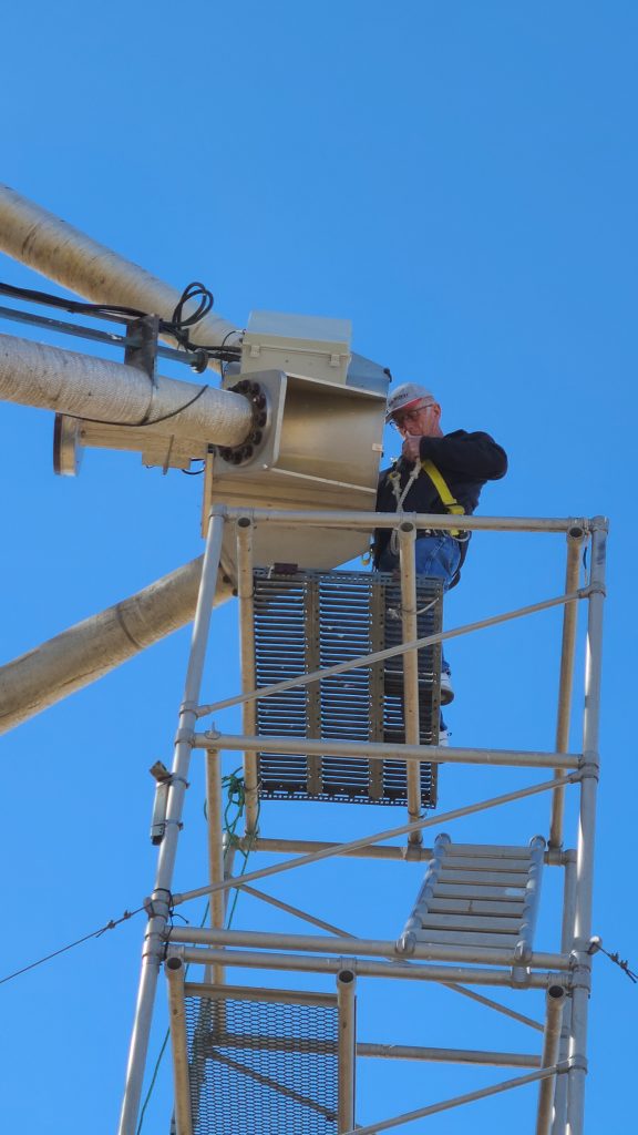
Ray Uberecken and Bill Miller went to the Plishner site on Sat. October 31.
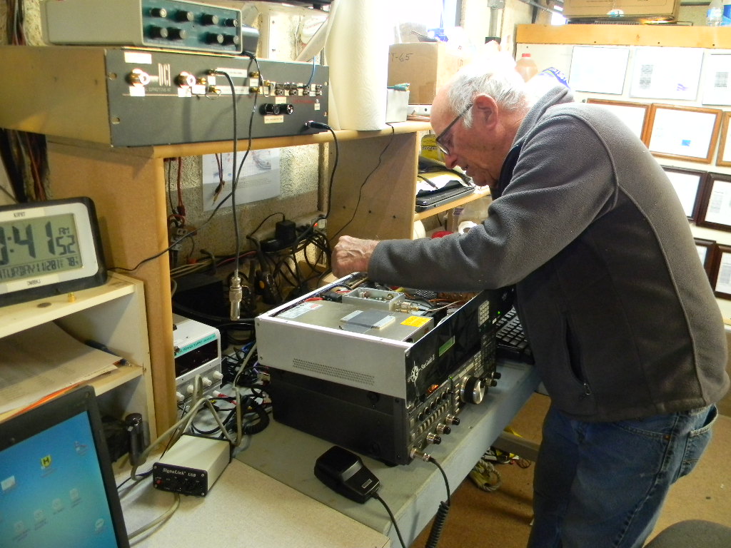
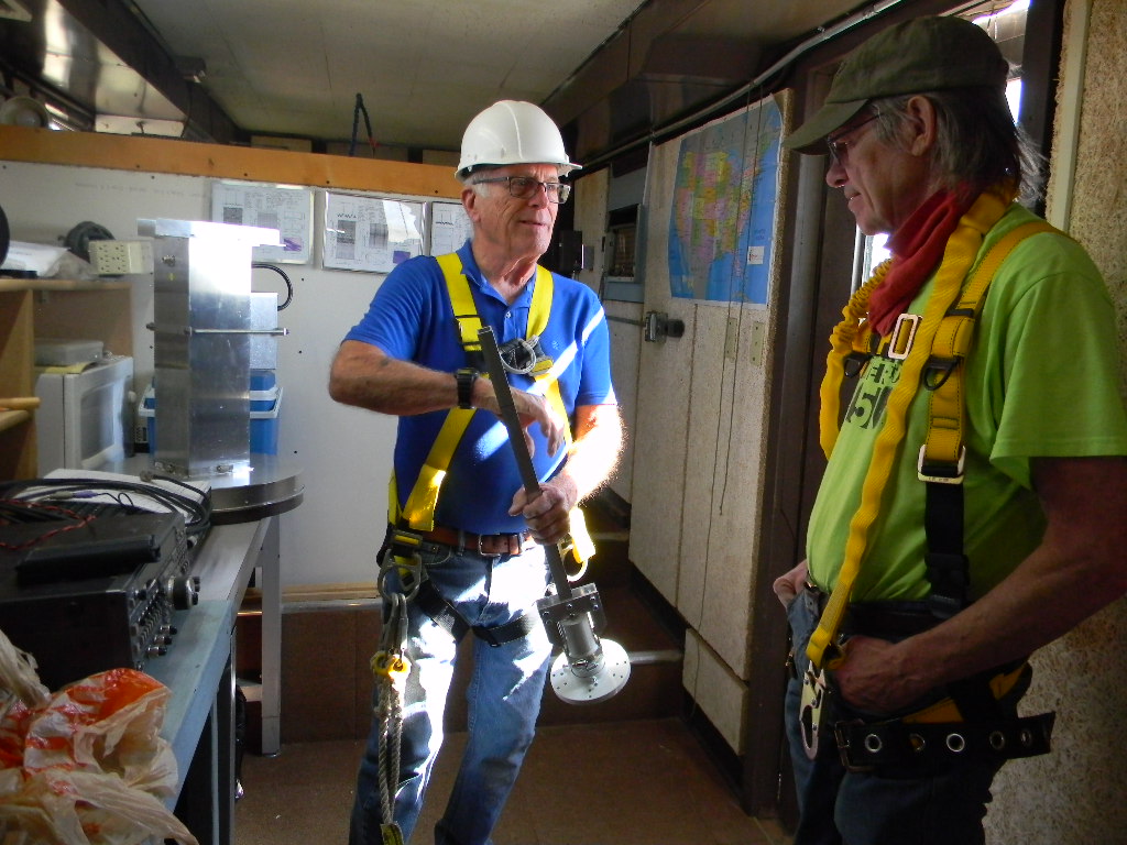
Ray brought back his EME 200 Watt amplifier box that he had removed on the previous weeks trip. The unit had blown a relay control FET that kept the unit in the transmit position so it would not connect the feed to the receiver. Ray and Bill donned climbing harnesses, scaled the scaffold, and installed the amplifier before the wind could start blowing about 11:00 AM at the site.
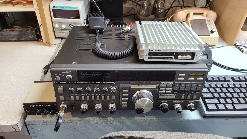
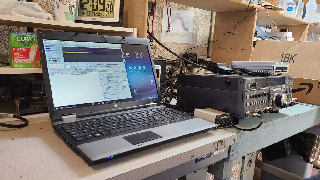
Ray also brought back the FT 736 Transceiver after repairing the seized tuning knob. He brought in a computer and an audio interface with JT-65 HF software loaded. This will enable digital mode EME on the next contest EME 50-1296 MHz — November 28-29, 2020. In addition, he installed an extra 1296 MHz 18 Watt auxiliary amplifier between the FT736 10W max output and the Amplifier at the feed point. This extra amplifier will enable the full power of the linear amp at the feed. Both the 18 watt amp and the 200 watt feed point amp are enabled with the Key circuit from the FT 736.
There is an extra power supply on the bench to power the 18 Watt amp and the key circuit to the feed amp is attached with the terminal block on the rack.
Ray also brought back the Electronic Keyer and Paddle for the FT736 moon bounce CW mode.
Once all this equipment was installed, we climbed the tower and replaced the bad swivel joint on the down feed coax with a short segment of very flexible RG8X cable to allow the cable wrap. Because this is the same impedance as the main hard line coax and very short it has insignificant loss to the signal.
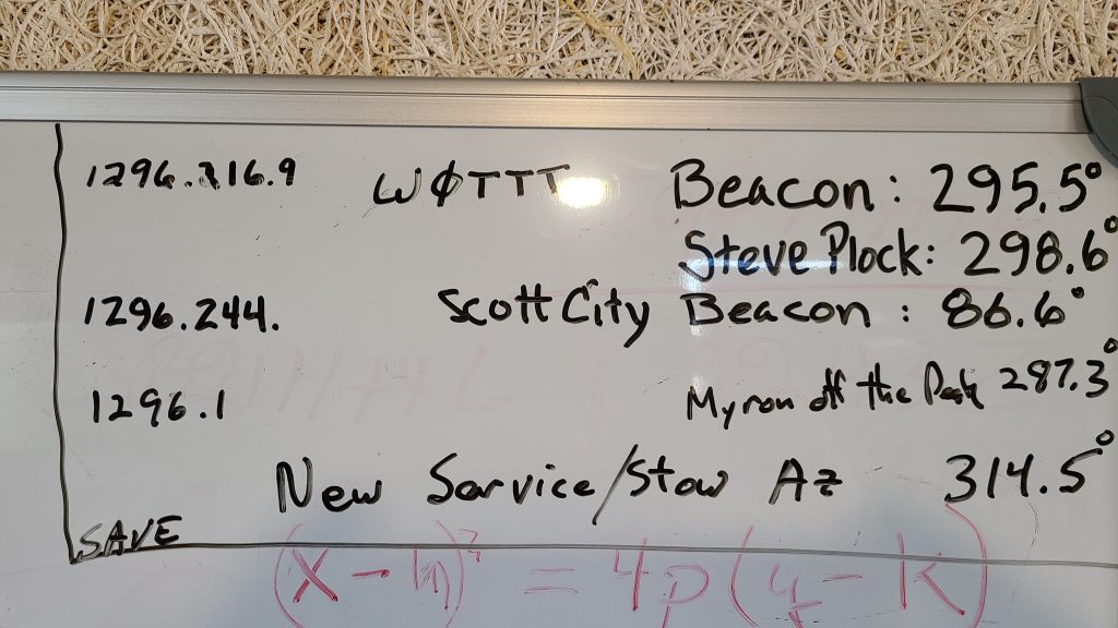
We then called Myron Babcock to test the equipment. We pointed the dish at Colorado Springs and at first did not hear his signal. He swung his antenna around to point at Pike’s Peak and we did the same and established communication on 1296.1 MHz with clear copy. This proved the overall system viability.
Bill set up his phone app and computer program for aiming the Hughes Net dish for internet. After using the compass to point the dish to the apps specified Azimuth and Elevation and working the dish around for half an hour, we still couldn’t get the modem to lock up and receive the satellite. More research is needed to make sure we are trying for the correct satellite and have the right coordinates and tools to do the alignment on the next trip. Once we have the Hughes Net system working, we should have high speed internet capability for a number of uses.
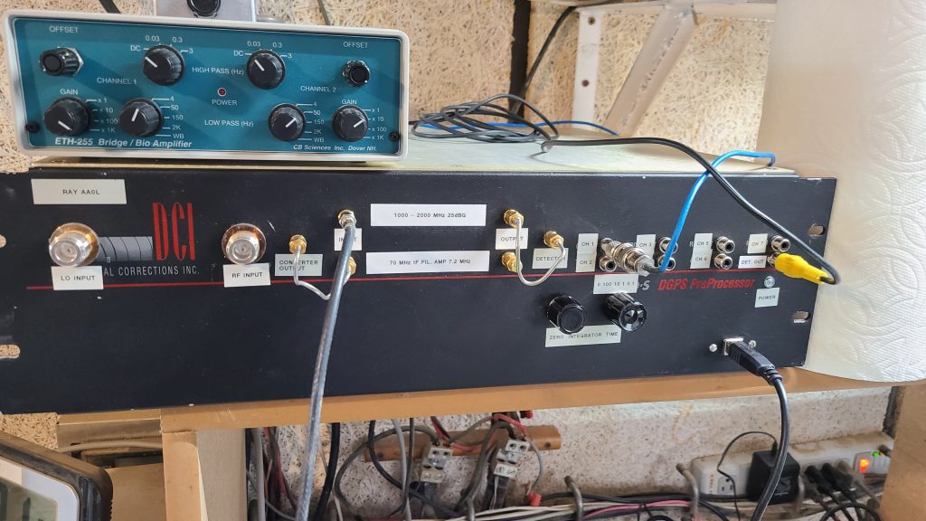
Ray has been working on his new radio Astronomy receiver based on a medical signal preconditioner and a stable amplifier/integrator and A/D converter. The receiver will give a greater bandwidth than current SDRs with up to 100MHz of bandwidth.
A conversion program is needed to convert the comma delimited tabular output of the A/D to the .Fil file format for radio astronomy. Ray installed the receiver and checked its operation.
We stowed the dish, shut everything down, removed the trash and locked the site. Note that the new service position on the scaffold after the recalibration of the pointing system is 314.5 deg. All old bearings for Beacons and such should be adjusted by -2.5 deg.
By Gary Agranat, with Myron Babcock and Glenn Davis. Videos by Bill Miller.
Friday evening at sunset as the team prepares for our first EME attempt overnight. Photo by Gary Agranat.
On Saturday October 10, 2020 we succeeded in making our first Earth-Moon-Earth (EME) Moon Bounce communications. We succeeded at our first attempt. This accomplishment was several years in the making, thanks to the work of many members, past and present.
We did this participating in the annual ARRL EME contest held on the weekend of October 10-11, 2020 GMT. (That’s Friday 6 pm to Sunday 6 pm local time.) The frequencies available for this contest were in the ham radio bands from 50 to 1296 MHz. We used our 60-foot dish antenna at Haswell, CO, with a 1296 MHz feed with dual circular polarization, installed 2 weekends earlier.
EME Moon Bounce communications is directing a signal to the Moon. The Moon’s surface simply reflects the signal back to Earth. If the Moon is above your horizon, if you have suitable equipment, and if you know enough about what to do, it would be possible for you to receive the signal and communicate back. You could communicate to your neighbor or across continents. The signals, however, are extremely weak, having to travel back and forth the Earth-Moon distance, over 238,000 miles. EME generally requires efficient directional antennas to sufficiently increase the signal gain. Amplifiers can be used too. And the antennas have to point to the Moon. Also, radio signals sent through the ionosphere experience a rotation in their polarization. And there is some effective rotation from other causes, including from the changes in orientation from the Moon and from operating on different points of the Earth’s globe. Our solution is to circularly polarize our signals. And also, there is a Doppler shift between transmitted and received signal, mostly due to the Earth’s rotation, causing a difference in velocity between the Moon and our location on Earth. All of these are challenges to deal with.
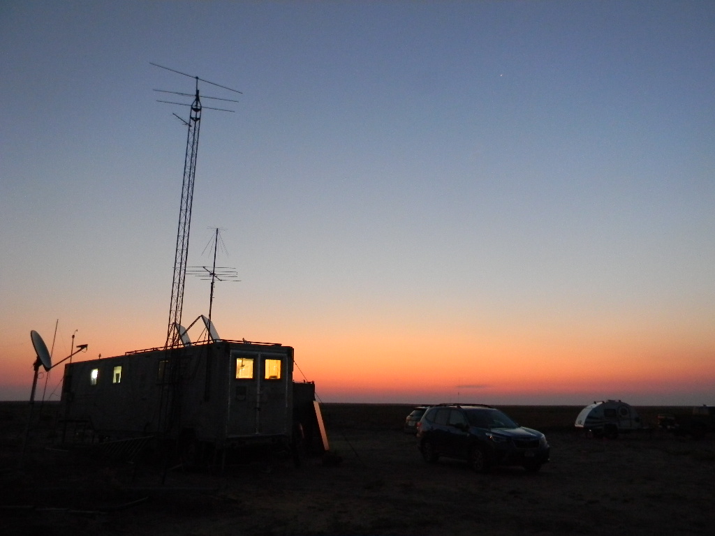
Our 60-foot dish antenna at sunset as we started preparations. Photo by Glenn Davis.
Our team for the EME operation were Ray Uberecken AA0L, Myron Babcock KL7YY, Gary Agranat WA2JQZ, and Glenn Davis. Bill Miller KC0FHN also came on Saturday morning.
The team arrived Friday evening October 9, while we still had daylight, to set up and test. Testing included making pre-arranged tropospheric scatter contacts, which were successful. We also attempted to complete set-up of a Hughes Internet antenna, to give us Internet access, but that was not successful. We instead sometimes connected to the Internet using cellphones. Although the contest began at 6 PM local time, we had to wait for the moon to rise above the horizon. Moonrise for us was at about 11:30 PM local time, and the Moon was above our horizon until about 2 PM local time the next day Saturday. We chose to stay for just this one Moon pass, and not continue through Sunday, in order to not knock ourselves out on this first attempt.
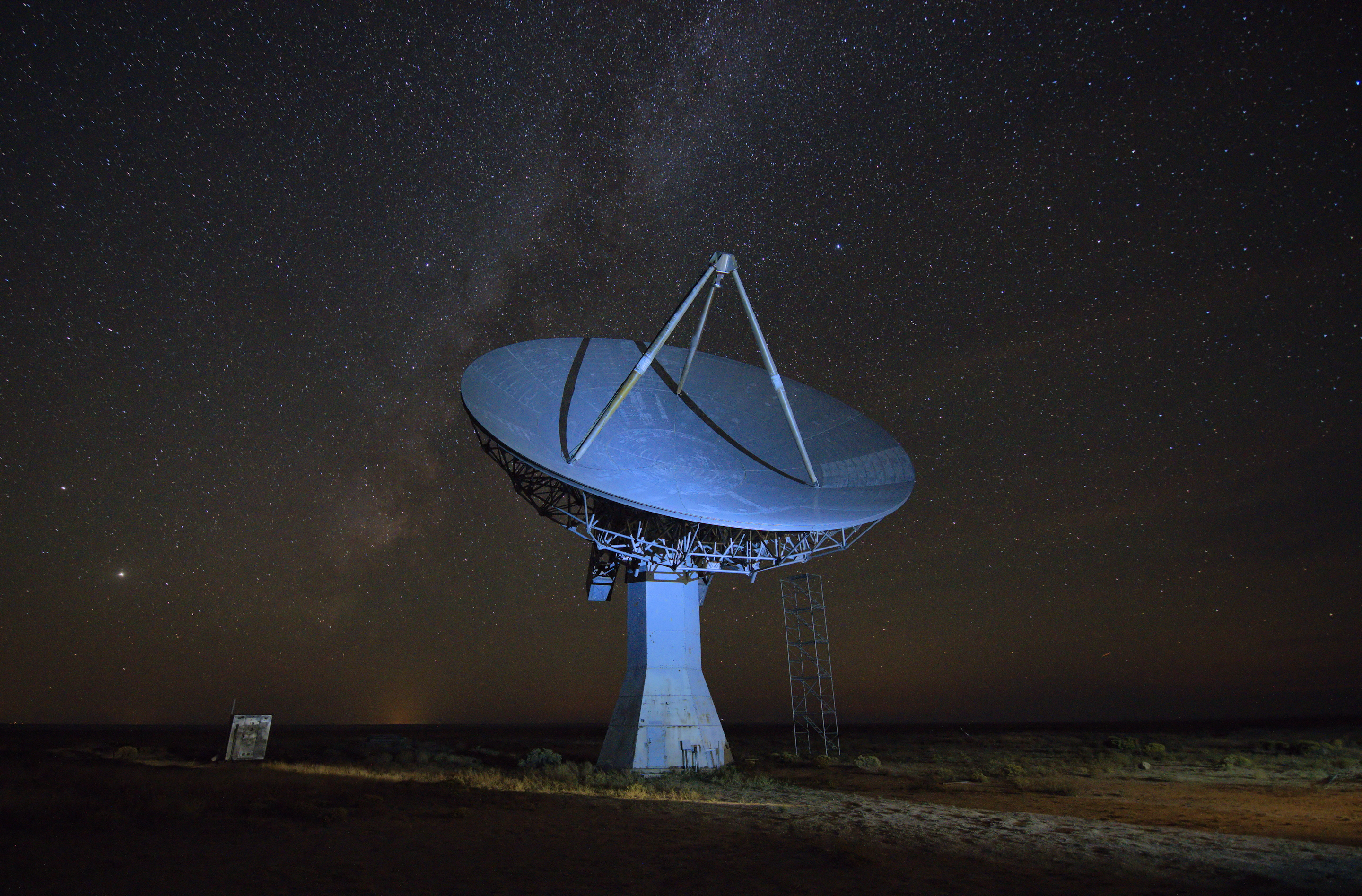
After we completed our testing, we relaxed until we were ready to start. Looking outside, we had an exceptionally deep starry sky. We could see the Milky Way clearly arching overhead through Cygnus. Jupiter and Saturn were bright to the south, and Mars was very bright, rising in the east. Glenn Davis experimented with his camera and took some nice time exposure photos with the dish antenna, the stars, and the Milky Way.
Photo by Glenn Davis. (Click to enlarge.)Our 60-foot dish antenna with the Milky Way. Jupiter and Saturn are brightly visible to the left of the antenna. Photo by Glenn Davis. (Click to enlarge.)
I (Gary) meanwhile got some rest. This enabled the others to get some rest later in the morning while I continued.
Myron KL7YY wrote and emailed an update about our operations to the DSES membership on Saturday morning at around 4 AM. It provides a good narrative of how we were doing until that point, and his update follows next:
* * * * * * * * * * *
Summary of DSES first attempt at EME, Earth Moon Earth, contacts using the 60 foot dish:
On Friday evening, October 9 we started with a few nearby Tropospheric Scatter contacts around 7 PM with DSES member KL7IZW, Steve in Monument, CO, and W6OAL Dave in Parker. Around 9 PM we talked to N0YK in Scott City KS, These contacts ranged from 110 to 130 miles and confirmed that our system was working.
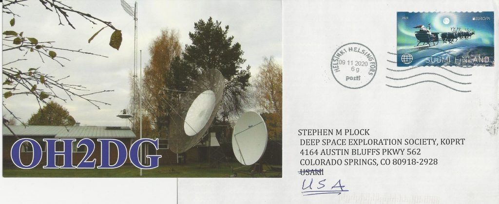
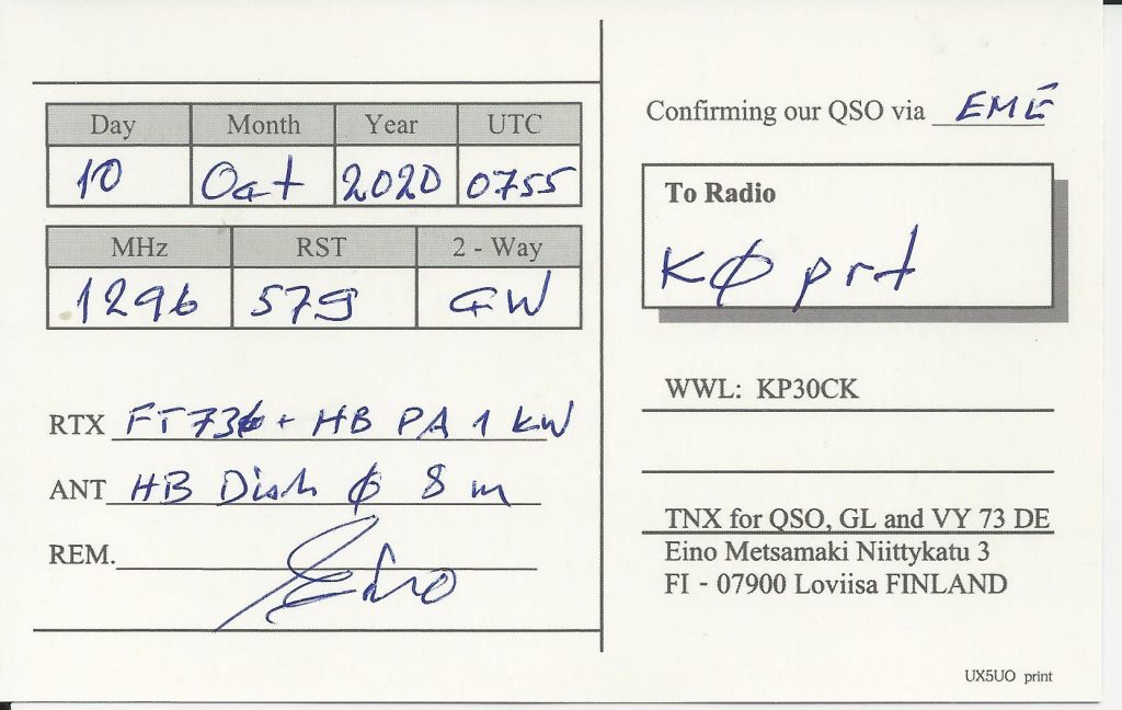
When the moon came over the horizon at midnight we tried to listen to the ON0EME moon beacon in Belgium but couldn’t hear it. About 45 minutes after moon rise we started to hear JT-65 digital signals. 10-15 minutes we started to hear CW signals. Glenn Davis made a few corrections to the tracking program and signals increased in strength. At times it sounded like a 20 meter CW contest pileup with all the loud signals bouncing off the moon all across 100 KHz of band (1296.0 to 1296.1 MHz). After about 90 minutes without hearing our own signal we rechecked the power to the amplifier at the feed horn and everything appeared to be normal. A few moments later we finally heard our own signal 2.5 seconds later on CW off the moon and the Belgium Moon Beacon. I made several calls on SSB and heard our echo really loud. We went back to CW and Gary proceeded to start making CW contacts. The first almost contact, a German station, abruptly dropped out so no official contact was completed. Our first official station worked on CW was with OH2DG in Finland. England was next followed by Italy, Poland, Denmark, Sweden and with DSES member Skip Macaulay, VE6BGT, in Alberta Canada.. Also made our first voice SSB contact with him as well. Seems that with every new contact we make it is with a new European country. In order to correct for Doppler shift and with no RIT we are changing VFO’s from Receive to Transmit by several KHz or more. Lots of CW signals being heard and we still have 12 more hours of moon to bounce signals off of… We are hearing our own echo and we have lots of hours to go. We plan on Digital mode later in the day but for now there are more than enough signals to hear on CW.
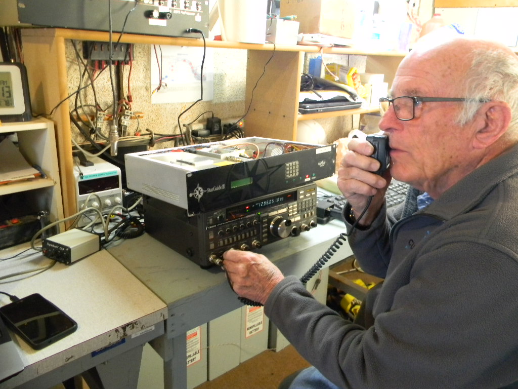
Our Moon bounce station consist of an older Yaesu FT-736R with 10 watts feeding almost 180 feet of half inch hardline into a 200 watt amplifier at the antenna feed horn. The receiver pre amplifier is a 30+db gain with a noise figure of minus .35. Our Effective Radiated Power (ERP) is over 6 million watts.
* * * * * * * * * * *
We operated with our club call sign K0PRT.
A short video of Myron KL7YY calling CQ. You can hear the echo of his signal coming back from the Moon a couple of seconds later. (Video length 35 seconds)
Because the signals are extremely weak, and there can be fading, there is a standard protocol for exchanging messages for EME contacts. This is intended to ensure as much of the message as possible can be copied and acknowledged on both sides. The basic format is simple, and one repeats a lot. One first exchanges call signs, then the signal reports, and then finally if that worked, an acknowledgement all that was copied correctly. If one only completes part of the contact, one should still log that, as that is an accomplishment. If using Morse Code, the standard is to send at 15 words per minute, but spacing out the characters longer than usual. The faster sending and spacing is to help one copy complete characters if there is fading. If one misses a character, one still has a high chance to get the character with the many repeats.
In order to have the proper frequency offset for the Doppler shift, we referenced the WSJT 10.0 software, at the suggestion of Steve KL7IZW. The software has an astronomical data section that calculates and displays the frequency offset. The higher the frequency, the more significant the offset. At 1296 MHz we had a difference of as much as 3 KHz between transmit and receive frequencies. The software also displays other useful data like local Moon rise and set times (based on Grid Square location).
The WSJT 10.0 software also can be used for JT65C digital EME communication. However, we didn’t figure out how to configure that in time with our setup, and so we didn’t do any digital contacts this time. We could tell we were hearing JT65 signals. They were present from 1296.05 to 1296.1 MHz, and we almost always could hear those signals while the Moon was up.
Glenn stayed up until about 3 AM, when we were sure our antenna azimuth alignment was correct and would continue to point accurately to the Moon. His work was invaluable in troubleshooting the azimuth offset, which turned out to be about 1.5 degrees, and honing in on the Moon once we heard CW signals.
Glenn Davis working with the antenna pointing. Photo by Gary Agranat.The 60-foot antenna pointing east, for the tropospheric scatter test to N0YC in Kansas. Later we would point east again, to prepare for where the Moon would rise. Photo by Gary Agranat.Myron making a tropospheric scatter SSB phone contact during testing, with Glenn Davis setting the antenna pointing. The scene was similar when me made SSB phone contacts during the EME contest. Photo by Gary Agranat.Myron, Glenn, and Ray. Ray was looking for the ON0EME beacon after the Moon rose. Photo by Gary Agranat.
Since the Moon rises in the east, our signal paths at first are to the east. That is to Europe and the North American east coast. As Myron mentions, once we started receiving the signals, we were hearing many European stations, and we were busy. Through the morning we made 14 contacts to Europe, to 8 European countries. We also made the contact to our DSES member Skip Macaulay VE6BGT in Alberta, Canada, on CW and then phone. W4OP in North Carolina, hearing us on SSB, then gave us a call on SSB too.
Ray AAOL brought a CW keyer that can send Morse Code with either a keyer paddle or a keyboard. It can store pre-programmed messages, like a CQ call. I (Gary) decided to use the keyer paddle, as that gave me more flexibility — I could quickly adjust for conditions — and I felt more comfortable as I am used to the key. Meanwhile, it seemed to me also that some of the CW contacts we made used software to send their messages. Those didn’t have good spacing between words or call signs. And that made copying slightly more challenging. A keyboard though can enable any of us to send, even if we don’t have practice sending Morse Code. Most of the contacts we made were with CW Morse Code.
This short video shows part of a Morse Code CW contact by Gary WA2JQZ. XE1XA in Mexico called CQ. We responded by sending our call sign K0PRT several times. Then K (the invitation to respond) several times. When we switch the VFO from the transmit to the receive frequency, you can hear the last part of our signal coming back, reflecting from the Moon, several seconds later. You then here the signal from XE1XA, also coming back reflecting from the Moon. He transmitted back our call sign as K0PRN, instead of K0PRT. We afterwards replied sending our callsign again, only, to give him the correction. That’s why we repeat a lot, and send sections of the message just one at a time. We completed the contact successfully. If you look carefully on the transceiver, you will see we switched about 2 KHz down from the transmit to receive frequency. (Video length 1:16)
At around 6 AM, when the Moon was high enough so that we no longer had a path to Europe, we took a break for breakfast and to rest.
Just before sunrise. Photo by Gary Agranat.Tracking the Moon during early morning. Photo by Gary Agranat.
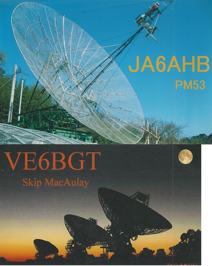
In earlier discussions we thought we might have many more contacts across the Pacific and to the North American west coast, when the Moon was sufficiently to the west. But it turned out we had very few contacts that way. We made just two contacts to Japan. Our first was at about 9 AM local time, to JH1KRC. Our second was three hours later to JA6AHB. Instead we made a few more contacts to the US, a few to Canada, and one to Mexico. These other stations we heard were searching around too. That led me to believe that if there were any other signals out there, we likely would have heard them.
W5LUA Albert Ward in TX, who some in our group know for EME. (He at first thought I was Ray, when I contacted him on CW. Myron then contacted him on SSB.)
W6YX, the Stanford University radio club, which was using a 28 foot dish. We contacted them first on CW. Then later when Bill was looking to record a phone QSO, which would illustrate the signal delay from the transit time to the Moon and back, W6YX just happened to call CQ on SSB on the frequency we were tuned to. We then had about a 4 minute QSO on SSB with them, which Bill recorded.
A video of Gary WA2JQZ responding to W6YX at Stanford University and having a 4 minute SSB QSO. (Video length 4:38)
We operated until about noon. We made 30 contacts in all. 25 contacts were CW (Morse Code) and 5 were SSB phone. 4 of the 5 phone contacts were with stations we also had CW QSOs with.
We submitted our contest log to ARRL the next day.
In the judgement of all of us, we had a very good EME operation. We are very pleased it worked so well on the first attempt. We clearly have a capable EME station.
Glenn and his team are continuing to follow up to investigate why we had a 1.5 degree azimuth offset.
It still takes my breath away to hear the echo of our signal coming back from the Moon, a couple of seconds later. The speed of light isn’t just a value in the books, it is something you experience viscerally first hand. It is real. EME is the longest signal path we have for communicating with others. This is fun.
These are the contacts we made. (CW = Morse Code, PH = SSB phone. Given also are the date and GMT times, the signal reports, and the other stations and their locations):
Total Contacts by State \ Province: AB 4, CA 2, TX 2, BC 1, FL 1, NC 1, NJ 1, WI 1. 8 total.
Total Contacts by Country: USA 8, Canada 5, Czech Republic 3, Federal Republic of Germany 3, Italy 2, Japan, 2, Austria 1, Denmark 1, England 1, Finland 1, Mexico 1, Poland 1, Sweden 1. Total countries 13.
Total Contacts by Continent: Europe 14, North America 14, Asia 2. Total continents 3.
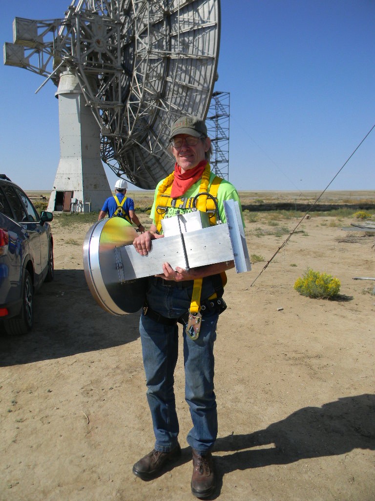
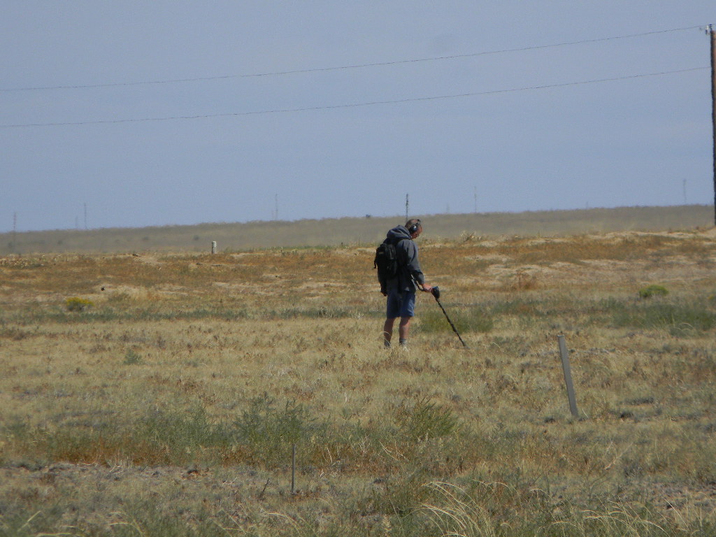
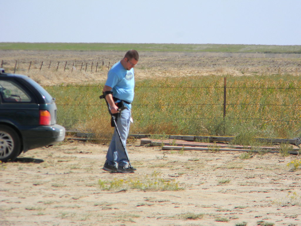
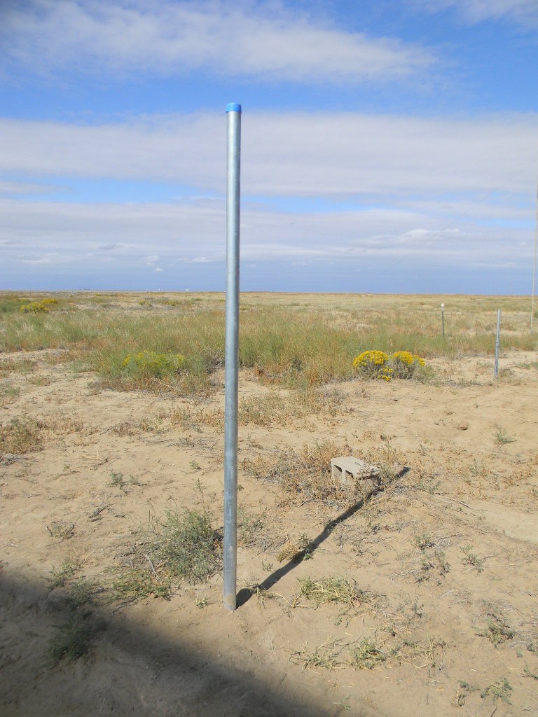
A DSES team worked at the Plishner Radio Telescope site in Haswell on Sunday September 27, 2o2o. Team members were Ray Uberecken, Floyd Glick, and Gary Agranat. We accomplished the main objective, to install a new 1296 MHz feed at the focus of the 60 dish antenna. We also installed a mast in the ground, on which will later be added a Hughes Internet satellite antenna. Two friends of Ray’s came out and did an immense service by using metal detectors and magnetic rollers to clear nails and other metallic debris on the site. We changed out two of the locks. And we inspected the bunker.
Mast for Hughes Internet antenna
Ray and I met at the Plishner site at 0930 in the morning.
We first installed a sturdy pipe mast behind the operations trailer, on which will be mounted a small satellite antenna to access the Hughes network geosynchronous satellite for Internet access. Ray chose a spot that will not be blocked by the trailer or the 60-foot antenna. We mixed cement and set the pole in its hole with the cement, using a level to check that the mast is vertical.
Moon Bounce (EME) Preparation
After that we manually rotated the 60-foot dish antenna to the service platform. I figured out, with Ray’s help and the checklists, how to use the software to monitor the antenna pointing. (Note: we might want to add a checklist just for this type of procedure, for using the software for just manual antenna pointing, as when we service the antenna.)
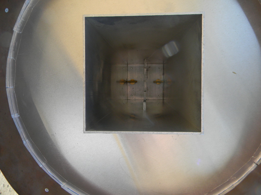
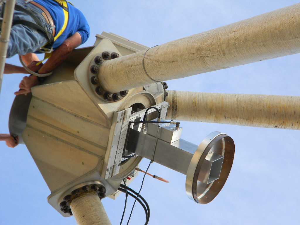
Floyd came out to the site by 1030. Ray and Floyd climbed the service platform. I worked on the ground to move feeds and tools up and down to them. We replaced the 408 MHz feed at the antenna focus with the newly built 1296 MHz feed. The 1296 MHz feed was built by KL6M, to specifications provided by Steve Plock (KL7IZW). The feed mount at the dish focus was designed by Ray, to enable the feed to more easily rotate out and be changed.
Conditions were somewhat windy, with a cold front coming, but still manageable. By the afternoon the winds had picked up enough that we postponed any further work at the feed. Work that still needs completion is installation of a 200 Watt amplifier at the feed. Since we are planning to operate at 1296 MHz from the Operations Trailer, which has a long coax hard line path to the pedestal and antenna feed, we expect significant power loss from the long path. We therefore need to boost the power again at the feed. We plan to install the amplifier the next weekend. We then also intend to test our setup by trying tropospheric scatter communications to the north.
We are planning to use this configuration to operate EME (Earth Moon Earth) Moon Bounce communications. And specifically we plan to participate in the ARRL EME contests on October 10-11, 2020 and on November 28-29, 2020 (UTC).
We discussed our plans for the upcoming contest in 2 weekends. The Moon then will be at last quarter phase. What that means is that it will rise on Friday night a little before midnight (about 1130 PM), and set Saturday a little after 2 PM. That means we will prepare to do overnight and morning operations. After the Moon rises we will try to pick up the ON0EME beacon in Belgium. We can try to contact across the Atlantic Ocean. The US East Coast will be in night time conditions, and so we anticipate less contacts to there. Daytime conditions, when more hams would be awake, are more favorable for the US West Coast, and across the Pacific Ocean to Oceana, Asia, and Australia.
Note that the 60-foot antenna will be configured with the 1296 MHz feed through the end of November. This will be an opportunity to try using it for other 1296 MHz communications, including troposphere scatter.
Metal souring of the site
A friend of Ray’s who works at Planet Granite Ryan, and his brother, Rob, came out to the site also. They have ground metal detectors and magnets on rollers, and systematically paced across the site to pick up nails and other small metallic debris. They did pick up lots of nails, including along the roadway. They spent a few hours with us, and left after lunch. They did us a great service by helping remove a lot of this debris.
Combination Lock and Bunker Inspection
We attempted to open the combination locks at the gate, the bunker, and the generator shack. After still having difficulty, we replaced the locks at the gate and bunker, with the locks Myron Babcock obtained for us. These are similar model locks, and the combinations were kept the same.
We had a report that the bunker had been flooded by two successive rain storms in July. We opened and inspected the bunker. The bunker was dry, though the floor had more-than-normal dust and dirt, and some tiny debris was spread here and there. It will require a fresh cleanup before normal use. We saw no indication of mold from dampness.
Tumbleweeds were accumulated again at the ramp entrance.
We completed our activities by early afternoon, about 3 PM.
For the team, – Gary
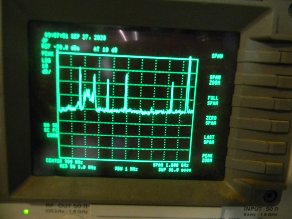
We kept the antenna steering in manual configuration. We opened the System 1 steering software to monitor the position angles as we manually steered the antenna to the service platform.We noted this radio interference at the site on our scope. This scan is from 0 to 1.8 GHz. The higher floor noise level at the left is from the sensitivity of our 408 MHz feed, which was still on the dish antenna, before we changed it out.The 60-foot antenna is positioned for service.Ray brought two feeds for the 60-foot antenna. This is Ray showing Floyd the 4 GHz feed, which we will use in the future, to calibrate the pointing position with geosynchronous satellites.Floyd carrying the 1296 MHz feed to the antenna for installation.The inside of the 1296 MHz feed. It is designed as a septum feed, with separate channels on each side for left and right circular polarization.Rob with a metal detector, crisscrossing the site, picking up small metal debris.Ray and Floyd on the 60-foot antenna service platform, starting work.Removing the cover.Ray is disconnecting the 408 MHz feed, so that it can rotate down and out for changeout.The 408 MHz feed is now rotated down. It is connected simply by the shaft to the mount, for easier changeout.Installing now the 1296 MHz feed. Its design doesn’t use a shaft, but instead will be securely fastened to the mounting frame.Ryan using a metal detector on the west side of the site.Our view towards the west. High clouds in the distance are an indication of a cold front gradually coming this way. We experienced steady windy conditions as the front approached..Closing up.Our view of Haswell in the distance. The clouds from the front were getting closer. By the time we left in mid-afternoon, the clouds were over us, but we had no precipitation.The 1296 MHz feed installed.We installed this ground mast. It will mount a small satellite antenna, to connect to the Hughes Internet network.