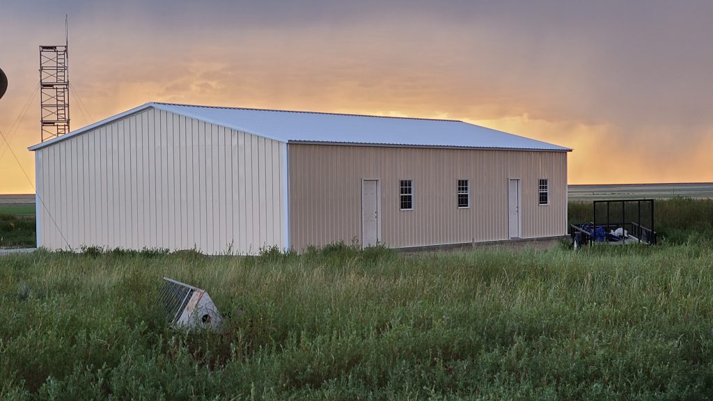
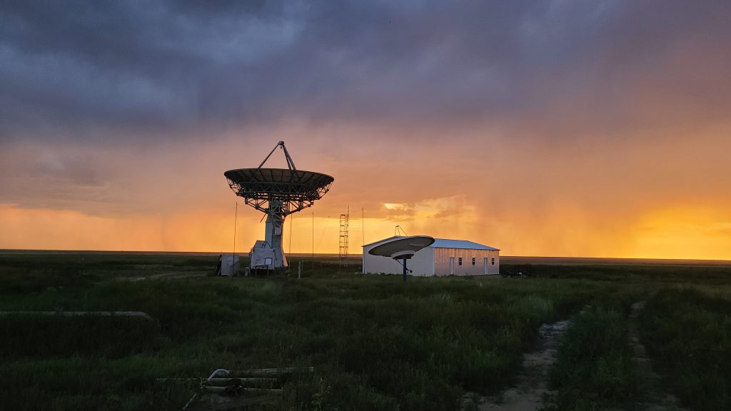
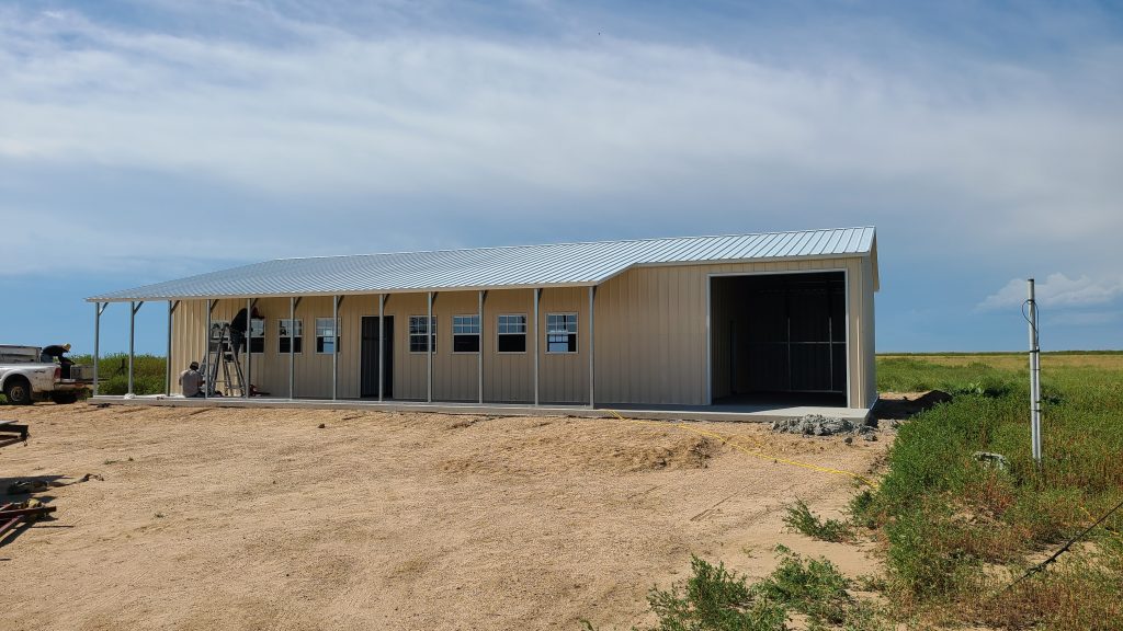
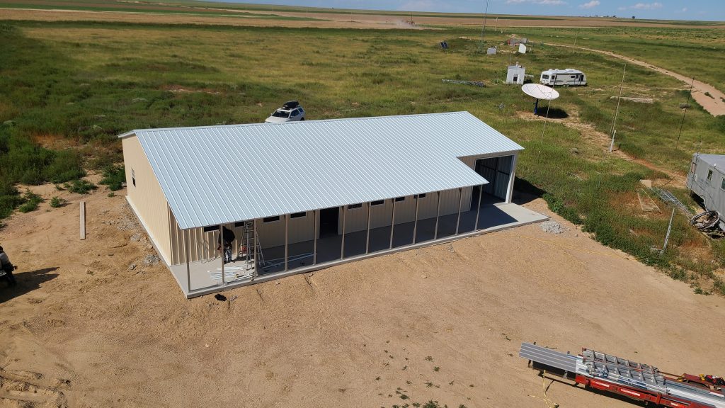
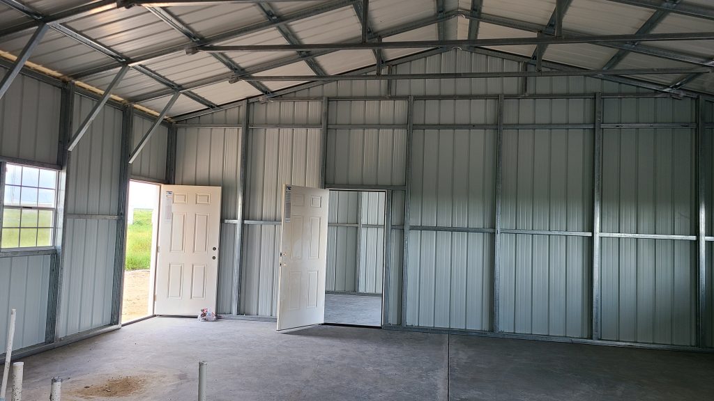
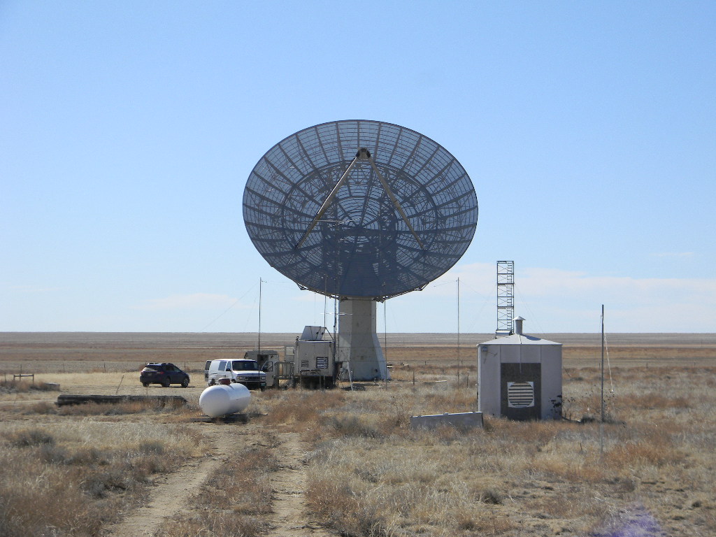
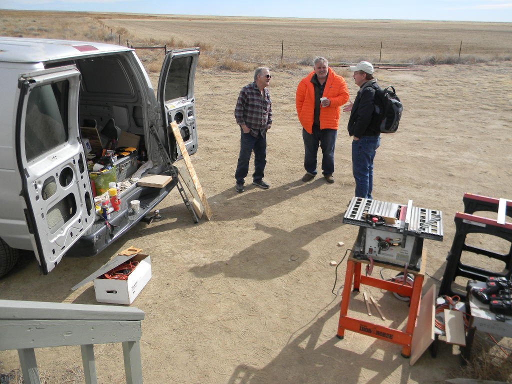
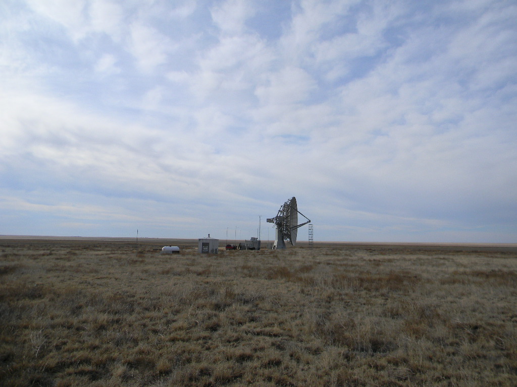
An update on the progress of our DSES building project. Our DSES Vice President and Project Manager, Bill Miller, has spent many hours and has made many trips down to the Plishner Site near Haswell Colorado to make this project happen. After many delays, some due to COVID, in finding contractors for concrete, plumbing, and electrical as well as building manufacturers to provide a 60-foot by 30-foot structure, DSES has finally made some progress. We still have many hours of interior/exterior work and antenna towers to place before we can move our current operations from the existing communications trailer and the underground bunker. This future work will still require many trips and hours on site to complete these tasks. We hope our local Colorado DSES members will be able to provide some help in completing these projects. DSES will provide dates and times of these trips so members can plan their time at the Plishner Site. A big thank you to Bill Miller for taking on this project and to those other members who were able to assist him over the past few months.
Lewis Putnam and Glenn Davis worked at the Plishner antenna site on Monday November 1. Lewis wrote this trip report to describe what they accomplished. The major reason for the work trip was to evaluate the mount pointing errors after the replacement of 1420 feed.
On Tuesday 12/08 Ray Uberecken and Bill Miller traveled to the Plishner site. We found that the gate chain lock was not properly attached to the post and could be removed without unlocking it
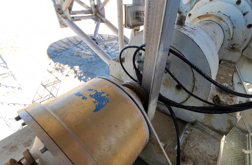
We replaced two of the coaxial cables running from the dish pedestal control deck to the upper deck just below the dish. These cables had stretched from their own weight and from the elevation rotation of the dish. As a consequence the center pin pulled out from the mating connector, losing the conductivity. We added to the cable a loop over the elevation axis. Ray added a feedthrough connector attachment on the ceramic slip ring collar, in order to remove the rest of the hanging stress on the wires, and he re-added the swivel joints below that. This arrangement completely eliminates the cables traveling up and down thru the collar as the elevation is changed, and this also virtually eliminates the coaxial cable wrap in the control deck area. We redressed all of the cables there with tie wraps and tape to get them out of the way of personnel in the deck and to remove the mechanical strain on all the cables.
At the top deck we removed the AC extension cord, which had been temporarily installed to a power amplifier at the feed for EME. Its cord insulation might not have survived the winter, and the uninsulated cord could potentially short out to the structure. A more permanent and reliable 120 volt power distribution is needed to the feed point.
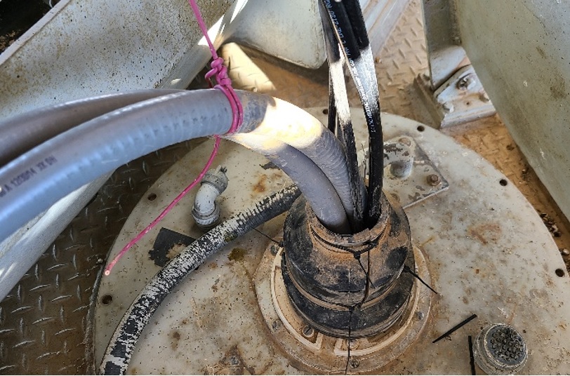
We also re-dressed all the wires and coax cable in the upper deck. We reused the pipe grommets as a weather shield for the cables going down thru the azimuth axes collar to the control deck level.
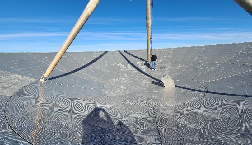
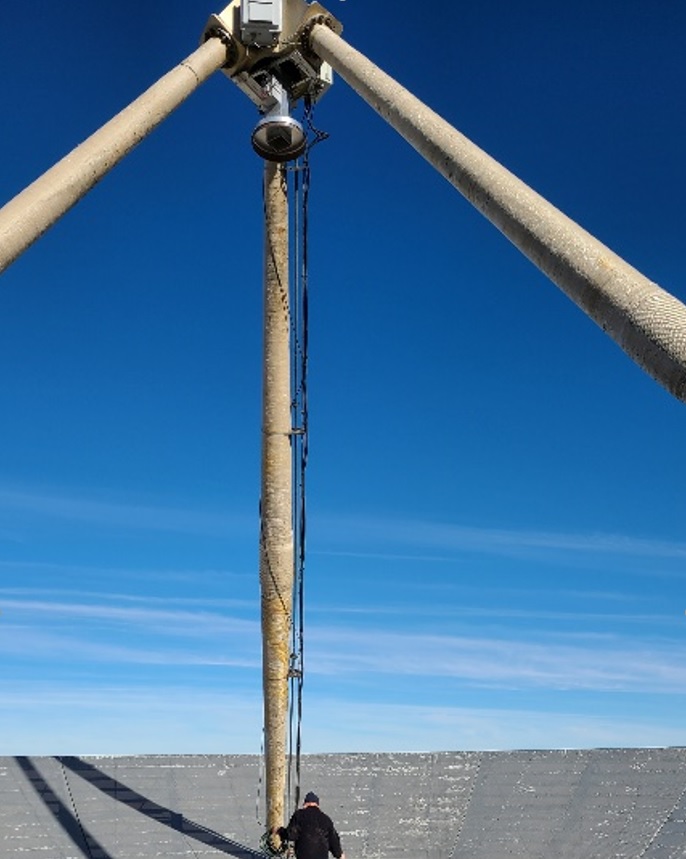
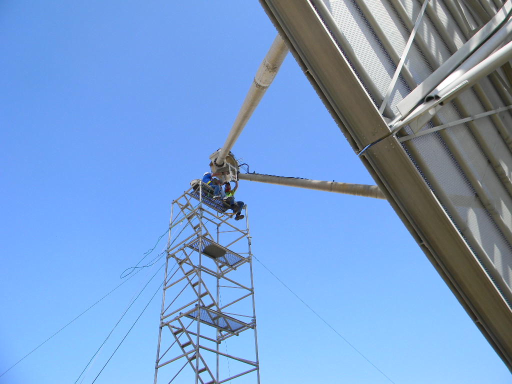
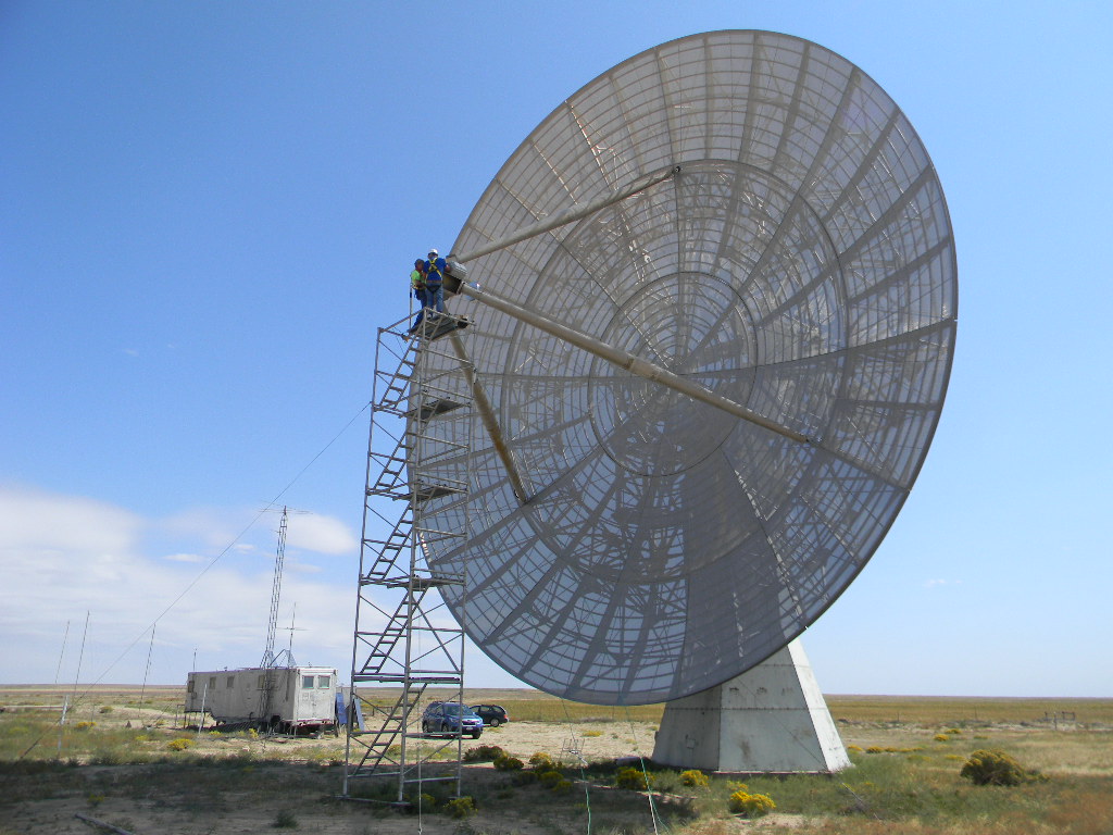
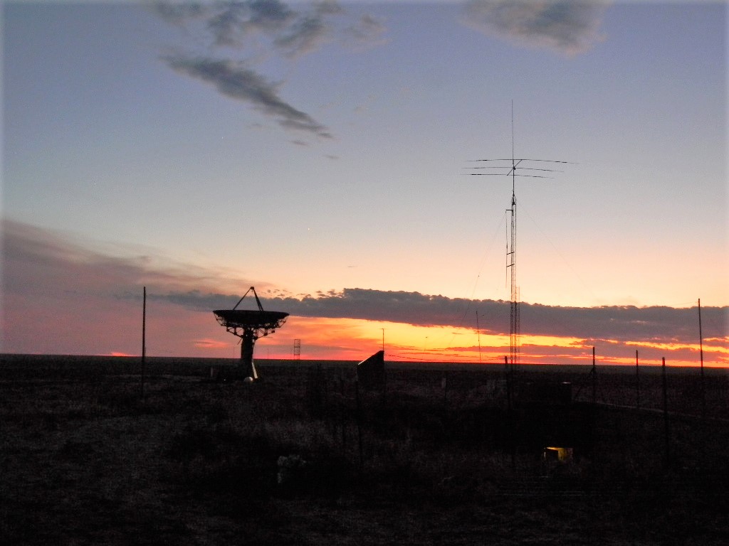
We then placed a ladder on the mount and proceeded up to the dish surface. There we continued to remove the 120 volt extension cord, and we inspected the surface and the support. This is a wide angle shot of the scene in the dish. It does give a sense of the surreal feeling of the view from there.
Wide angle view from atop the dish.
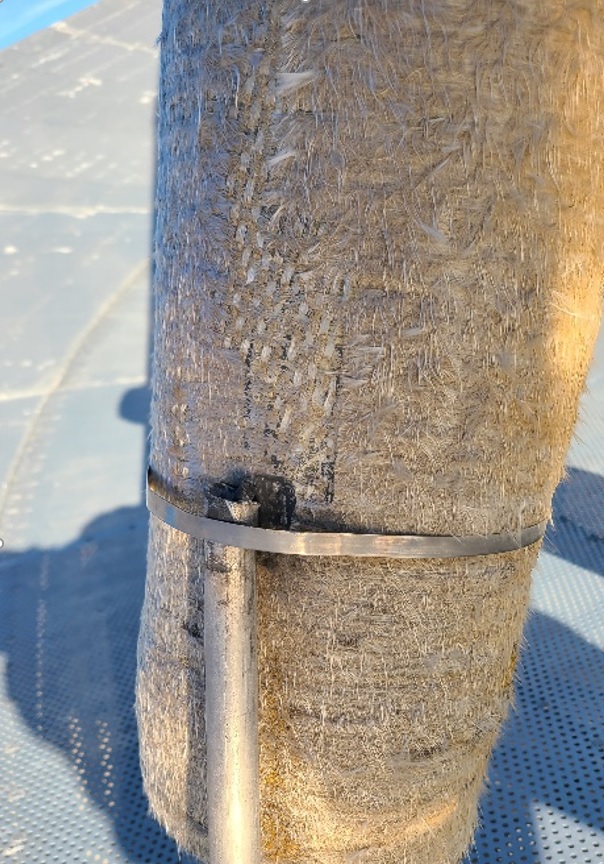
We inspected the attachments and connections. We discovered that the grounding cable connection on one of the legs leading to the focal box had been cut off. Furthermore, the wave guide that is attached at the dish structure is not electrically attached to the focal point box. Therefore the only ground to protect from RF, lightning, or static is the coax shield and the low voltage control cable ground wire. This may be one of the causes of failures in the electronics. We should retrofit to provide a good DC ground connection between the feed box at the focal point to the pedestal.
The ground cable cut, near the dish end of the support arm.
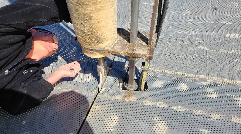
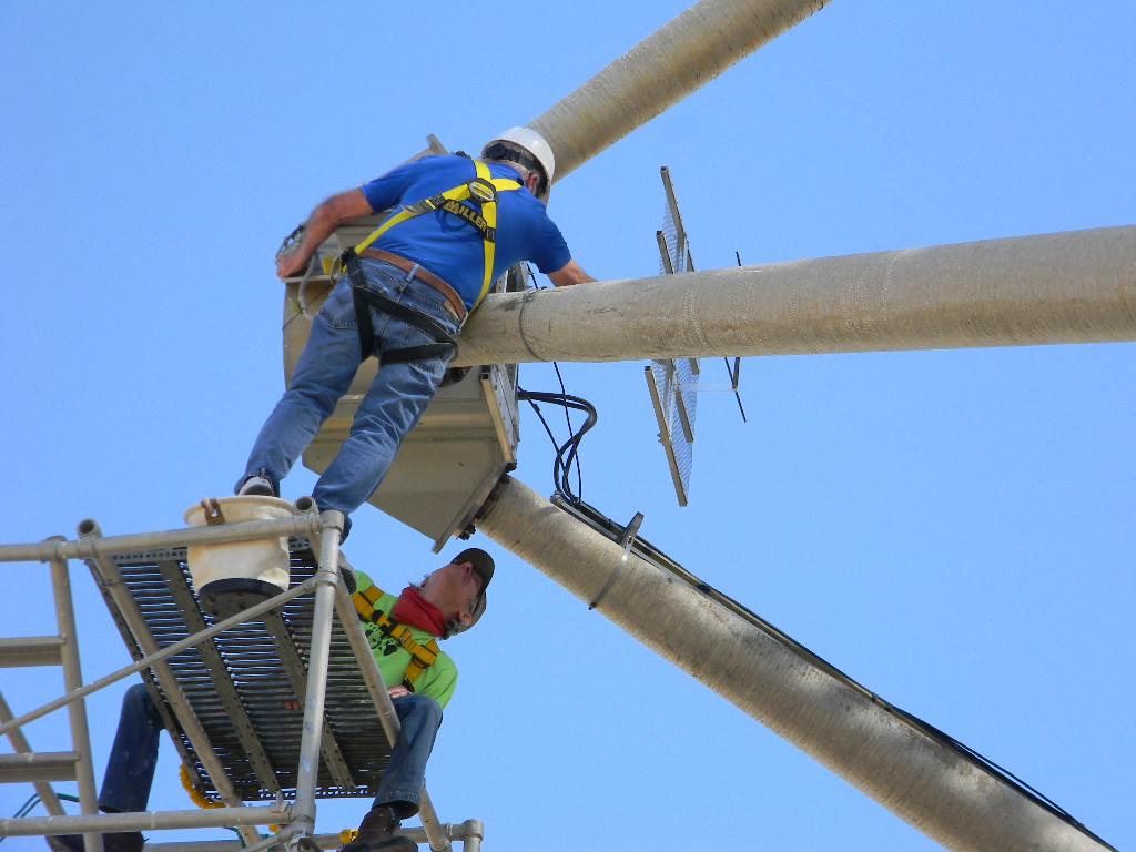
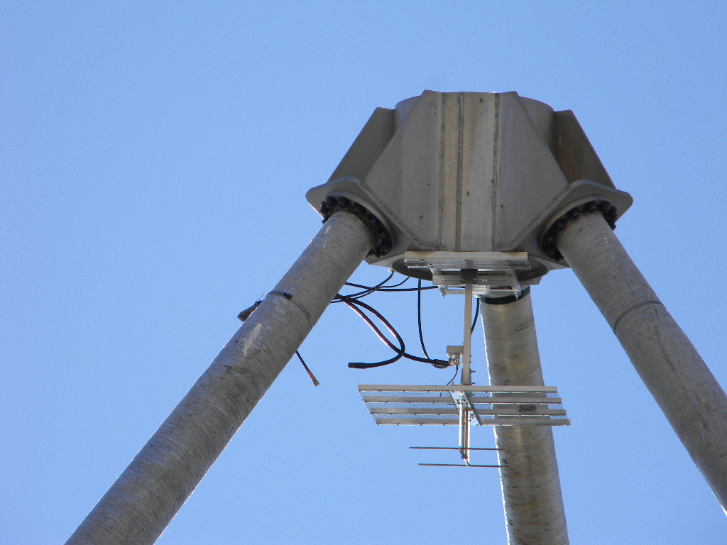
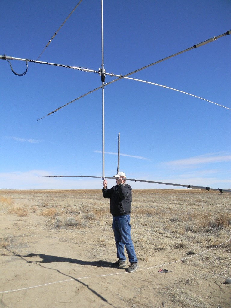
We also wanted to know how the fiber glass supports for the feed are adjusted.
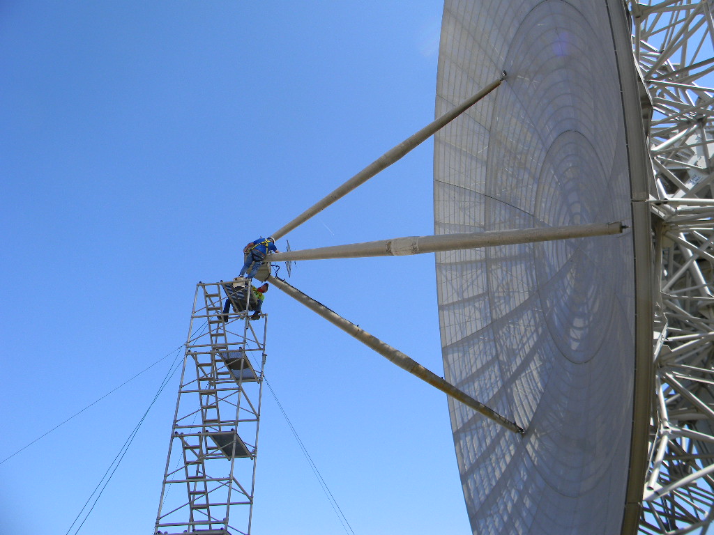
The fiber glass supports are badly weathered after 60 years in the open. We should derive a plan to rework the fiberglass surface, for the next time we rent a bucket lift to work on them.
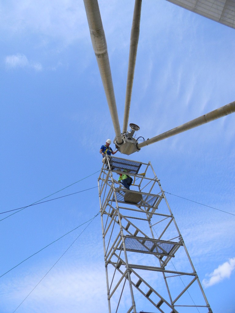
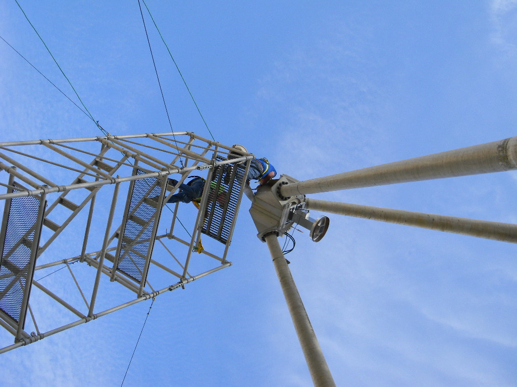
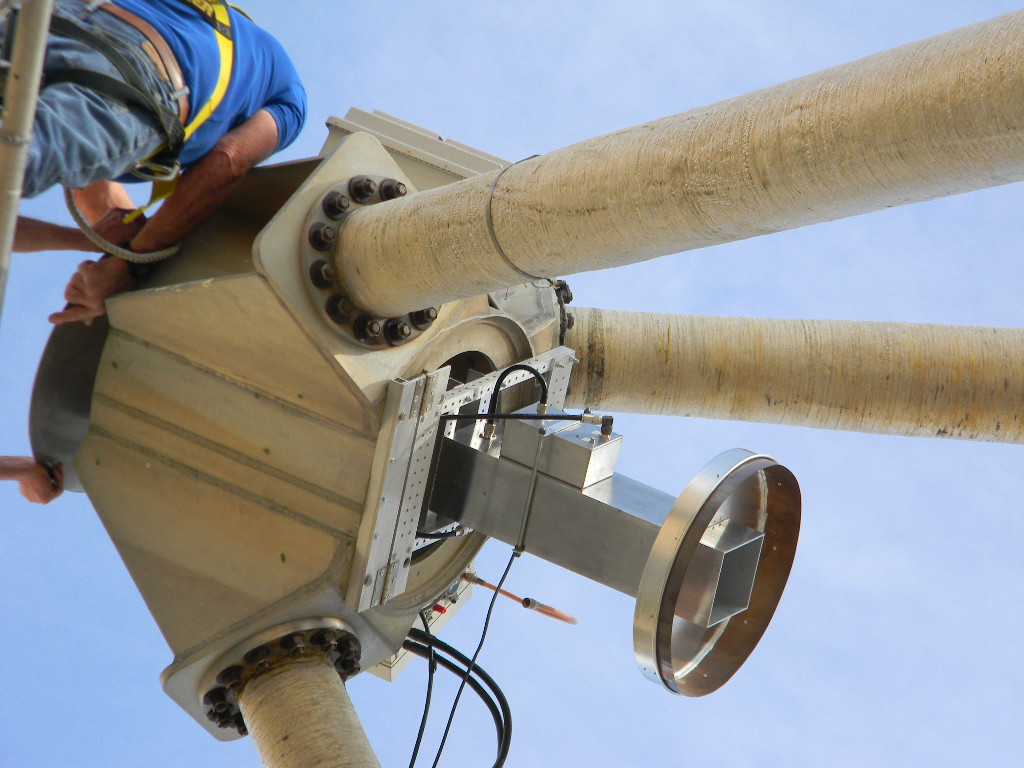
Full view of one of the dish’s support arms that supports the feed.
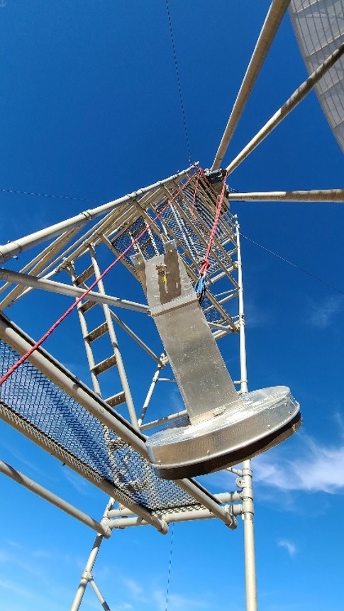
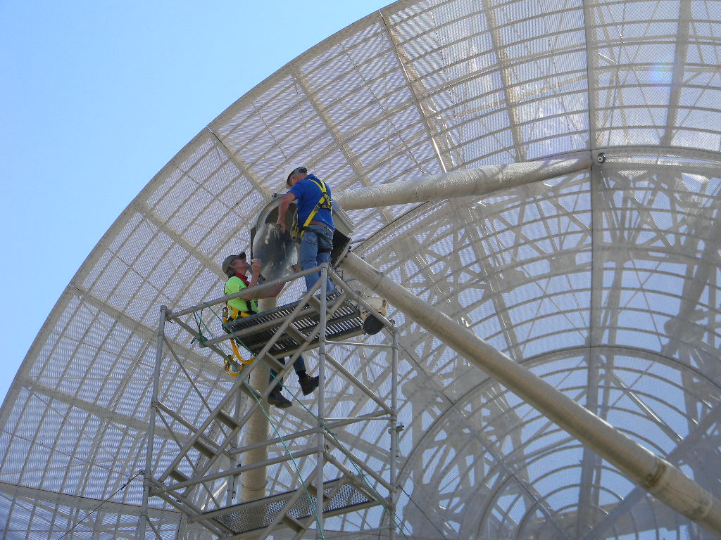
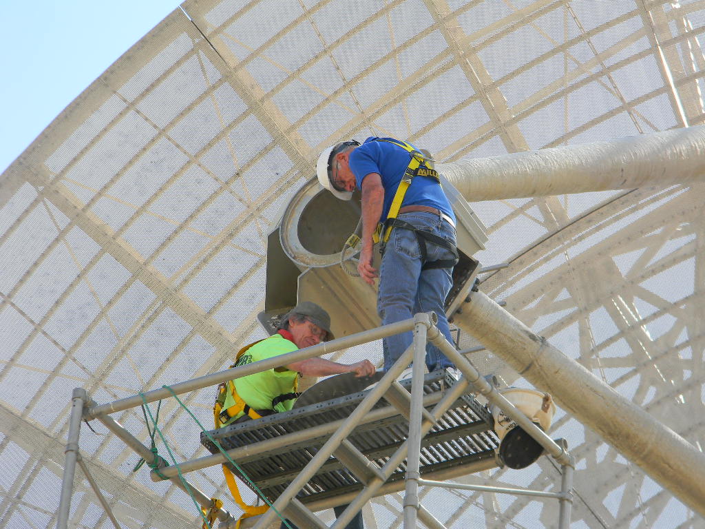
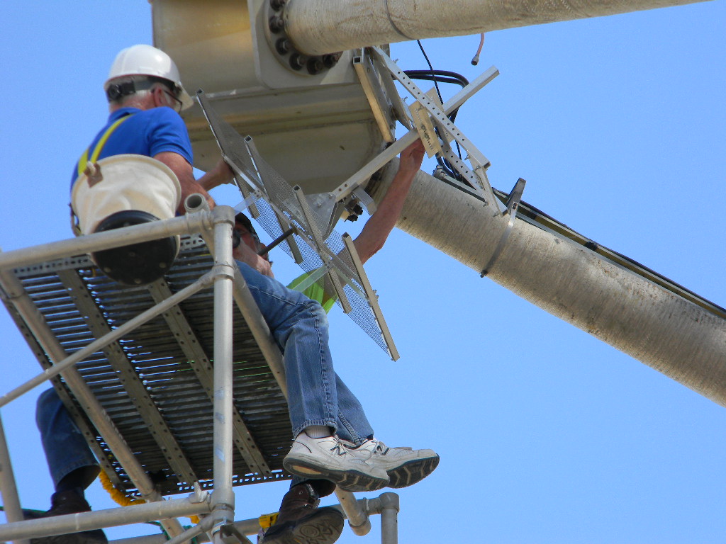
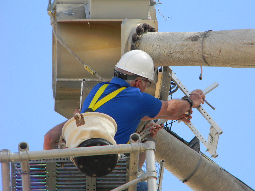
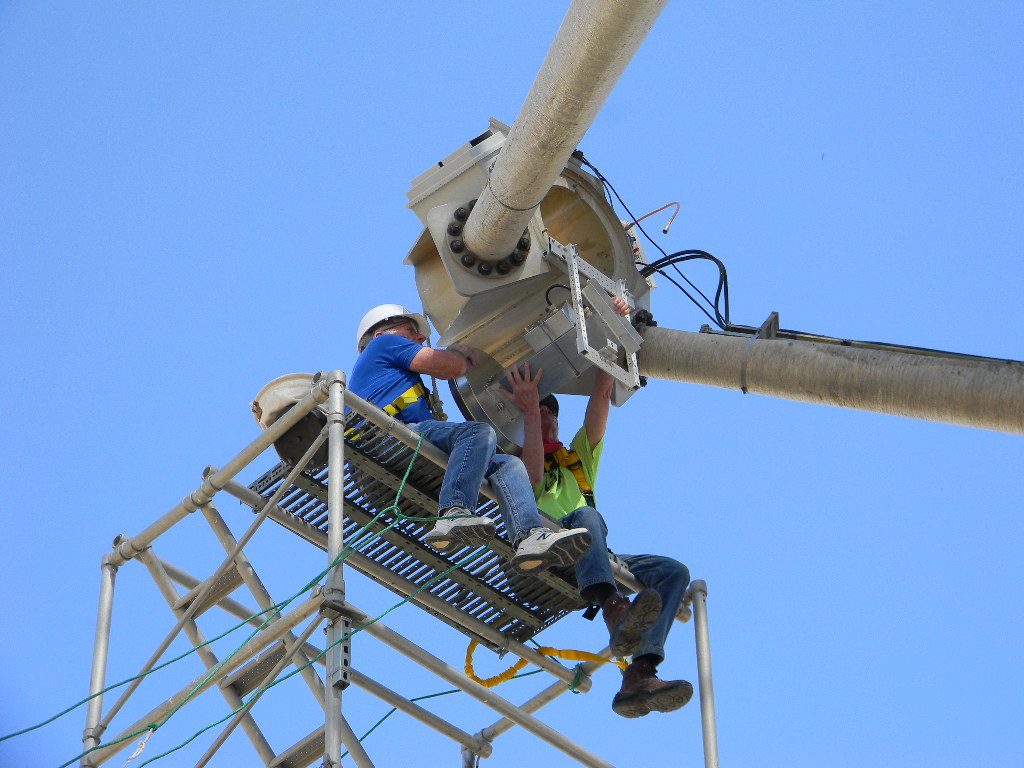
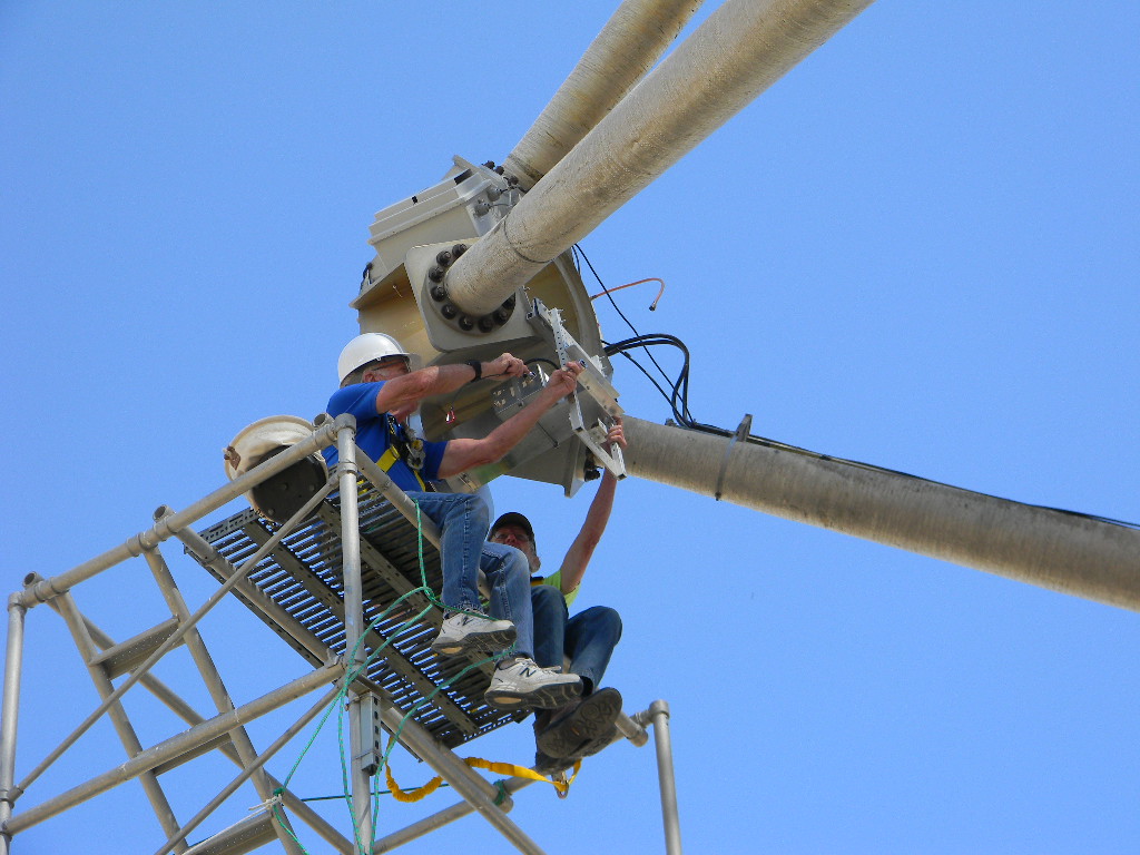
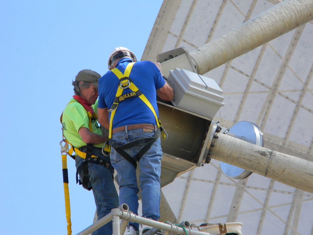
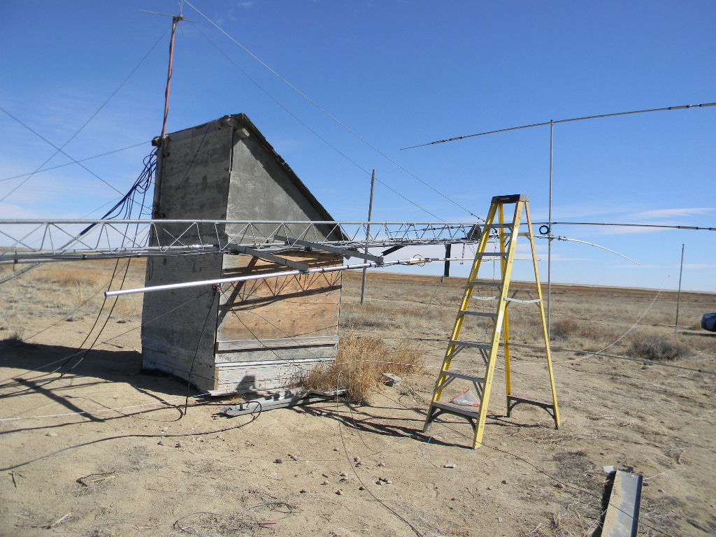
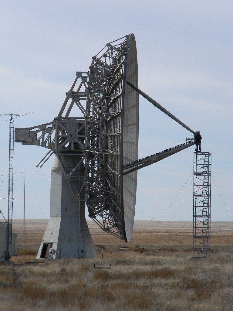
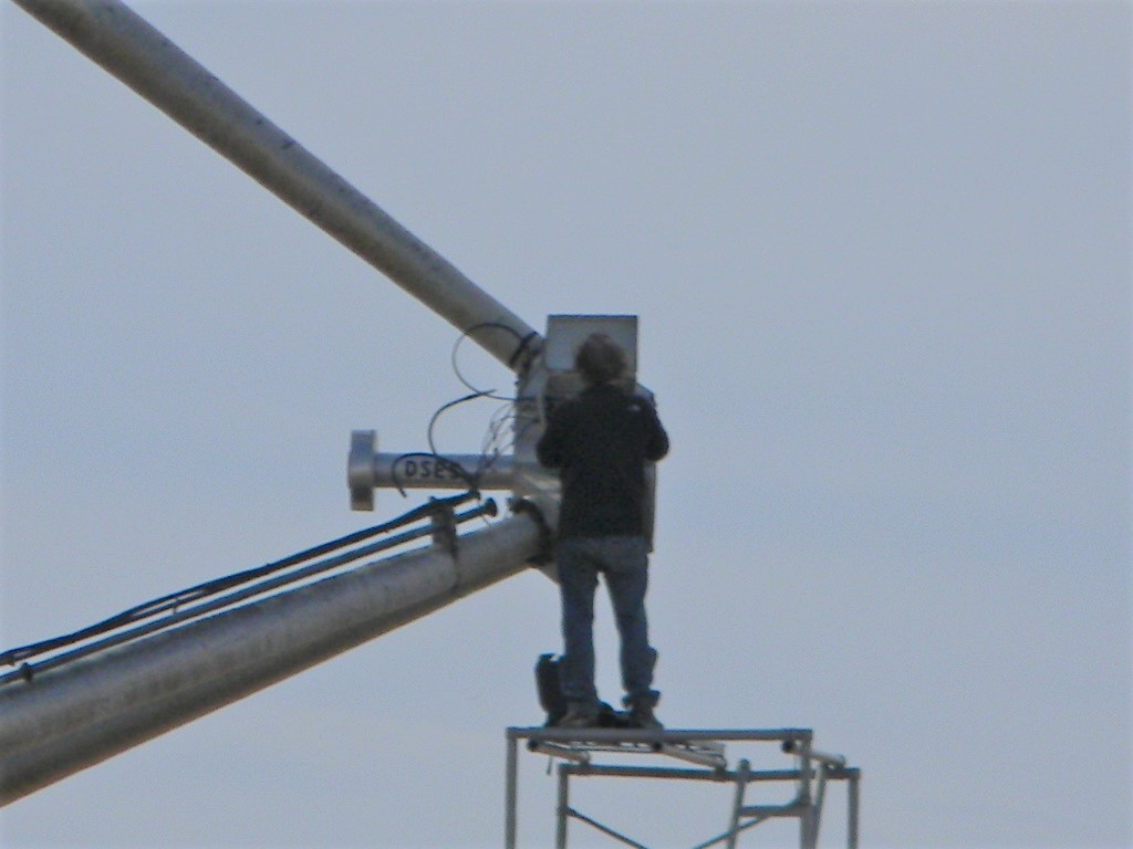
Once we had inspected the dish, we tipped the dish down to the service elevation, donned climbing harnesses, and climbed the scaffold tower. We removed the 1296 MHz feed and installed the 408MHz antenna using Ray’s quick-change mount. This only took about an hour where before the process could take as much as half a day.
Lowering the 1296 MHz feed antenna from the dish focus.
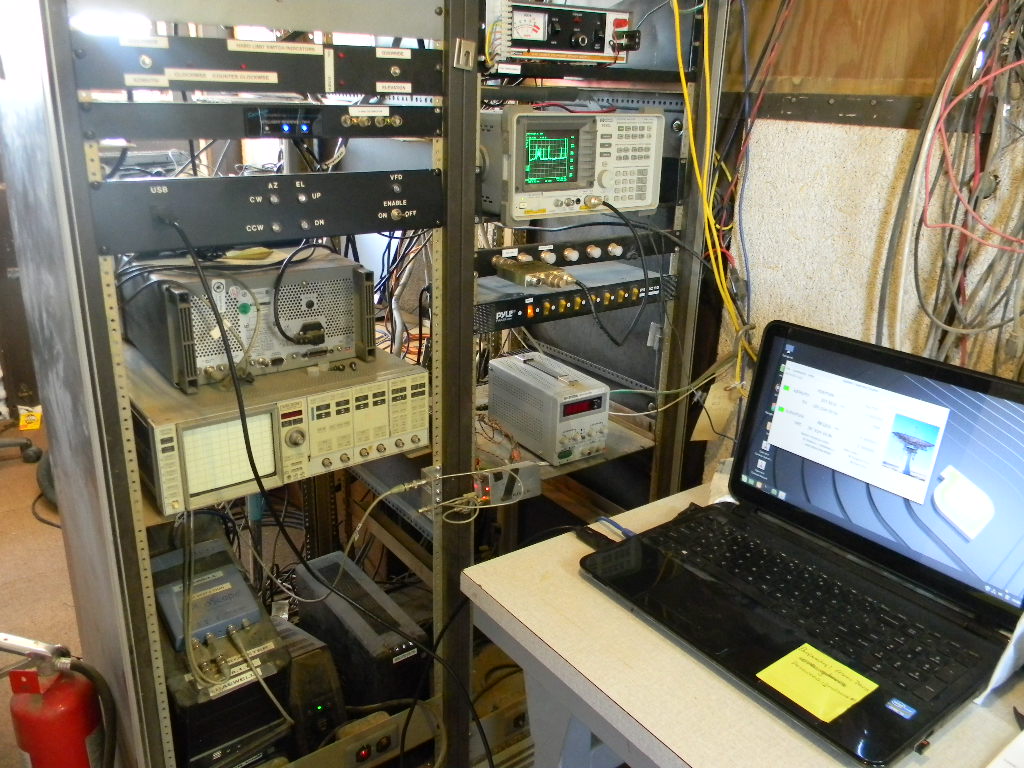
We also reworked the connector attachments in the electronics box. Ray then reattached the additional 20db amplifier, and checked everything out with the TDR and Spectrum analyzer. He reattached the cables in the pedestal to connect the correct coax lines to the Comm. Trailer.
Bill replaced the broken window in the back of the comm. trailer with the new one he purchased from Kent Glass and sealed it with RTV. This provides a much clearer view of the dish from the trailer.
We parked the dish, turned off all the equipment, locked the site and left for the day.
2020-11-23 DSES Science Meeting Notes, by Bill Miller
We had 16 participants in the virtual science meeting today: Thanks everyone for joining.
Participants: Dr. Rich Russel, Ray Uberecken, Lewis Putman, Bob Haggart, Don Latham, Floyd Glick, Gary Agranat, Glenn Davis, Jay Wilson, Jon Ayers, Lauren Libby, Myron Babcock, Robert Sayers, Ted Cline. Jerry Espada, Bill Miller
Agenda and notes;
Also see the Zoom Video Recording for more detail:
Myron’s Treasure’s Report Checking $1774.28. Savings $5742.15. We have 49 paid members.
Science Fair:
Bill spoke with Carol Bach the coordinator, she replied, “The Pikes Peak Regional Science and Engineering Fair will be held virtually on February 20, 2021. We are hoping that the Deep Space Exploration Society will again sponsor a special award or awards at the fair. In addition, we are hoping you or another member of your group will consider being a special awards judge. We will send you a code to unlock a showcase with digital displays that you can view. Virtual judging will take place between February 18-20, 2021.”
Bill to send board DSES Special awards criteria for approval.
“Please respond by December 2, 2020 to this email and confirm that your organization is planning to participate. Also, please let us know the name and contact email for future communications.”
Planet Walk:
Bill will write an endorsement letter and have the DSES Board modify and approve for Planet Walk Colorado Springs. See https://www.planetwalkcs.org/
Arecibo Failure:
See Bob Haggard’s repost on the Arecibo Radio Telescope status.
Problem with the 1296 feed last trip. Took down the Feed amplifier and found that the unit was stuck in the transmit configuration again due to a failed FET in the Relay driver. Fixed this and added more gate protection circuitry to solve the problem.
Also had a bad diode and a bad cable that had to be corrected.
The FT-736R Keyer connection failed on last trip but Ray fixed it.
Tried CW EME but couldn’t hear the echo.
Did receive Rays Home Based beacon bounced off Pikes Peak and verified pointing so the receiver chain is working.
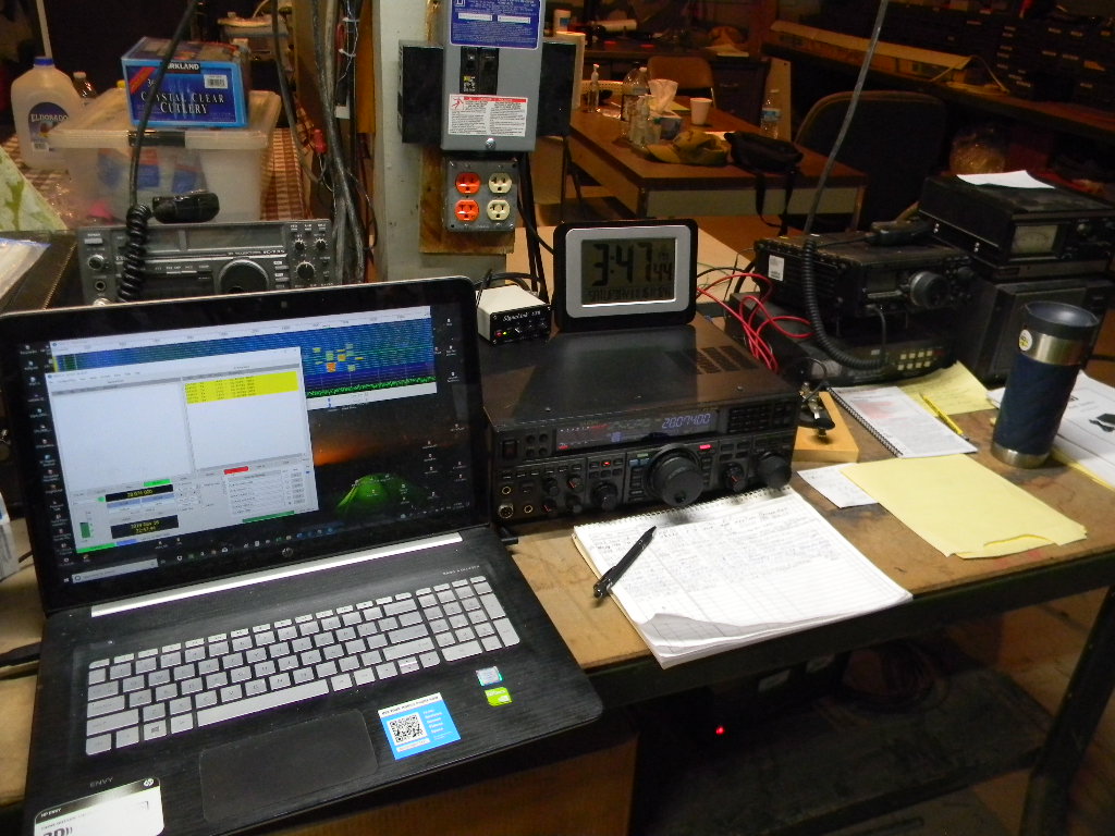
Gary Underground K0PRT bunker station summary report.
FT8, PSK Reporter website showed our station was received on 40 meters during afternoon in CA and TX.
15M operation was hot
Our rare grid square (DM88) attracted many Japanese stations
Vertical working well on 15 and 40 meters. 10 meters was tried and at least had good SWR, but band was dead.
Yagi was also working well to Japan
PSK reporter showed good coverage on 15 meters all around the Pacific Rim.
See more in Rich’s slides above
Glenn says that Phil is working on an elevation tracking update that will need some onsite testing when ready.
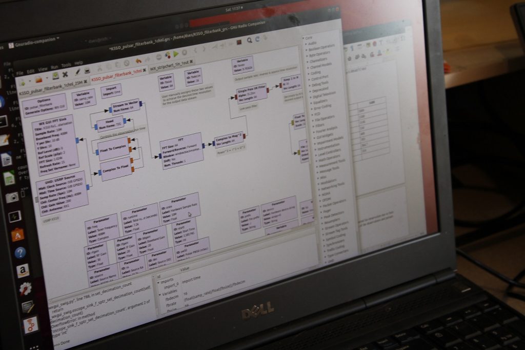
Much discussion about the SDR receivers, GNU SW and the computer power needed to run them. See the meeting recording for too much detail to capture here.
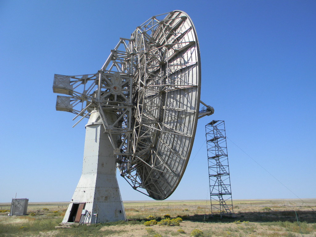
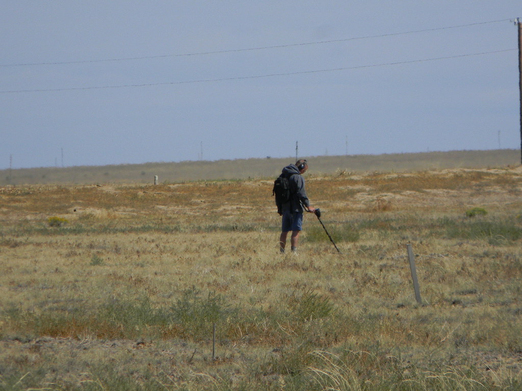
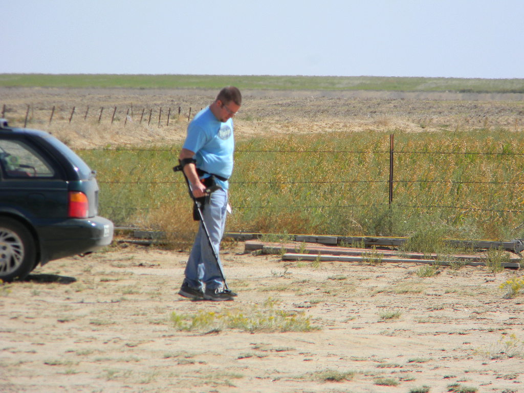
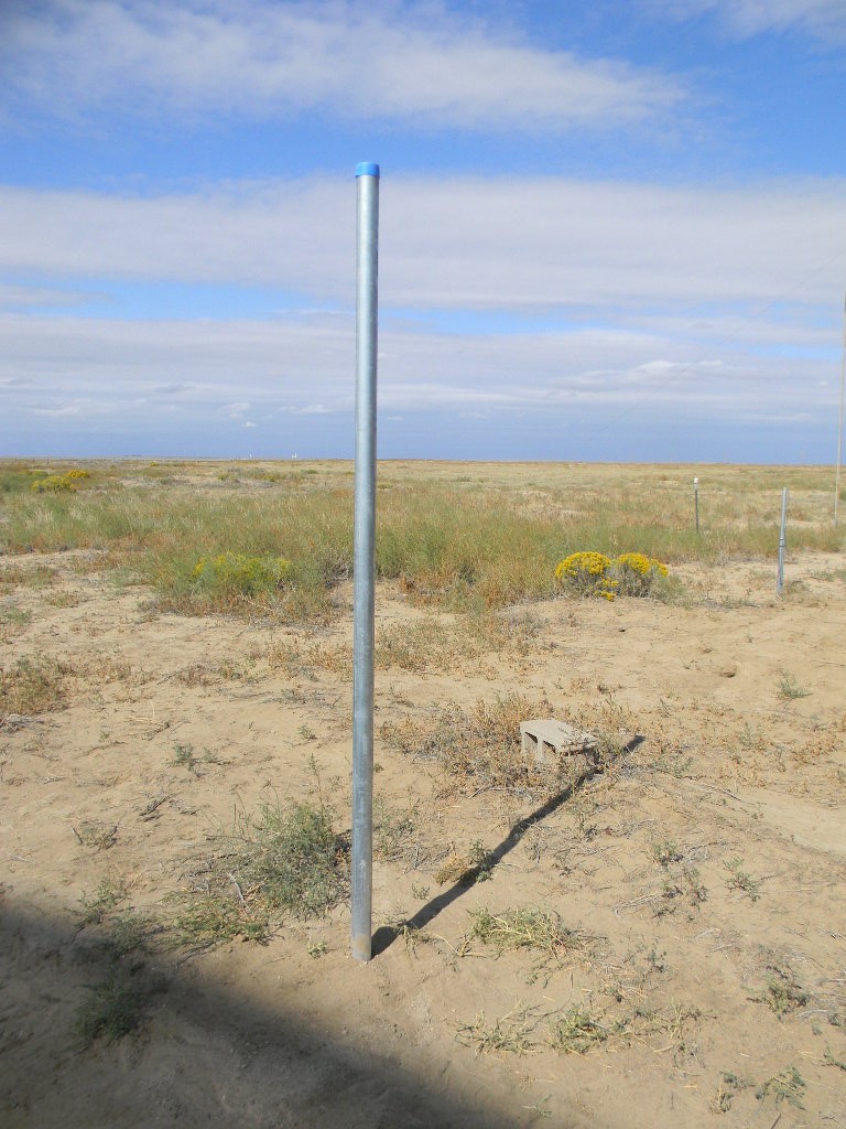
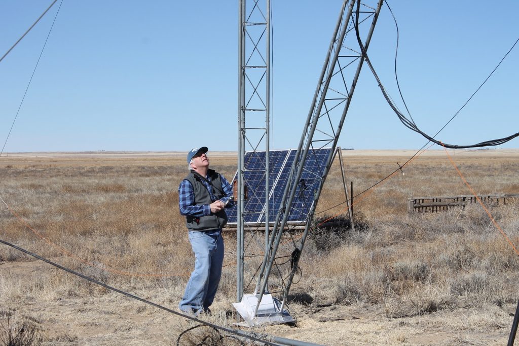
A DSES team worked at the Plishner Radio Telescope site in Haswell on Sunday September 27, 2o2o. Team members were Ray Uberecken, Floyd Glick, and Gary Agranat. We accomplished the main objective, to install a new 1296 MHz feed at the focus of the 60 dish antenna. We also installed a mast in the ground, on which will later be added a Hughes Internet satellite antenna. Two friends of Ray’s came out and did an immense service by using metal detectors and magnetic rollers to clear nails and other metallic debris on the site. We changed out two of the locks. And we inspected the bunker.
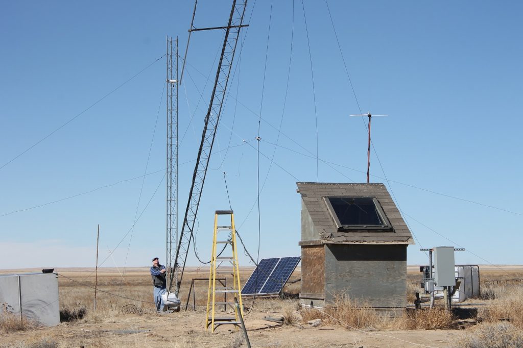
Mast for Hughes Internet antenna
Ray and I met at the Plishner site at 0930 in the morning.
We first installed a sturdy pipe mast behind the operations trailer, on which will be mounted a small satellite antenna to access the Hughes network geosynchronous satellite for Internet access. Ray chose a spot that will not be blocked by the trailer or the 60-foot antenna. We mixed cement and set the pole in its hole with the cement, using a level to check that the mast is vertical.
Moon Bounce (EME) Preparation
After that we manually rotated the 60-foot dish antenna to the service platform. I figured out, with Ray’s help and the checklists, how to use the software to monitor the antenna pointing. (Note: we might want to add a checklist just for this type of procedure, for using the software for just manual antenna pointing, as when we service the antenna.)
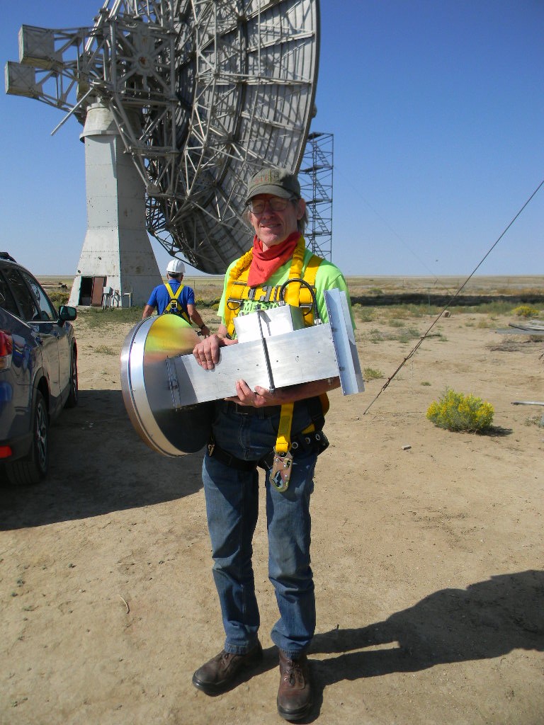
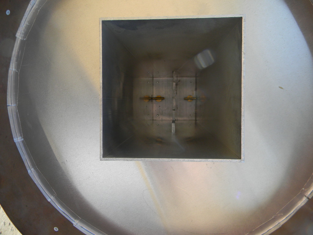
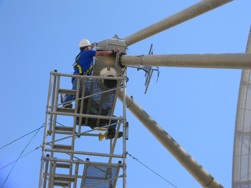
Floyd came out to the site by 1030. Ray and Floyd climbed the service platform. I worked on the ground to move feeds and tools up and down to them. We replaced the 408 MHz feed at the antenna focus with the newly built 1296 MHz feed. The 1296 MHz feed was built by KL6M, to specifications provided by Steve Plock (KL7IZW). The feed mount at the dish focus was designed by Ray, to enable the feed to more easily rotate out and be changed.
Conditions were somewhat windy, with a cold front coming, but still manageable. By the afternoon the winds had picked up enough that we postponed any further work at the feed. Work that still needs completion is installation of a 200 Watt amplifier at the feed. Since we are planning to operate at 1296 MHz from the Operations Trailer, which has a long coax hard line path to the pedestal and antenna feed, we expect significant power loss from the long path. We therefore need to boost the power again at the feed. We plan to install the amplifier the next weekend. We then also intend to test our setup by trying tropospheric scatter communications to the north.
We are planning to use this configuration to operate EME (Earth Moon Earth) Moon Bounce communications. And specifically we plan to participate in the ARRL EME contests on October 10-11, 2020 and on November 28-29, 2020 (UTC).
We discussed our plans for the upcoming contest in 2 weekends. The Moon then will be at last quarter phase. What that means is that it will rise on Friday night a little before midnight (about 1130 PM), and set Saturday a little after 2 PM. That means we will prepare to do overnight and morning operations. After the Moon rises we will try to pick up the ON0EME beacon in Belgium. We can try to contact across the Atlantic Ocean. The US East Coast will be in night time conditions, and so we anticipate less contacts to there. Daytime conditions, when more hams would be awake, are more favorable for the US West Coast, and across the Pacific Ocean to Oceana, Asia, and Australia.
Note that the 60-foot antenna will be configured with the 1296 MHz feed through the end of November. This will be an opportunity to try using it for other 1296 MHz communications, including troposphere scatter.
Metal souring of the site
A friend of Ray’s who works at Planet Granite Ryan, and his brother, Rob, came out to the site also. They have ground metal detectors and magnets on rollers, and systematically paced across the site to pick up nails and other small metallic debris. They did pick up lots of nails, including along the roadway. They spent a few hours with us, and left after lunch. They did us a great service by helping remove a lot of this debris.
Combination Lock and Bunker Inspection
We attempted to open the combination locks at the gate, the bunker, and the generator shack. After still having difficulty, we replaced the locks at the gate and bunker, with the locks Myron Babcock obtained for us. These are similar model locks, and the combinations were kept the same.
We had a report that the bunker had been flooded by two successive rain storms in July. We opened and inspected the bunker. The bunker was dry, though the floor had more-than-normal dust and dirt, and some tiny debris was spread here and there. It will require a fresh cleanup before normal use. We saw no indication of mold from dampness.
Tumbleweeds were accumulated again at the ramp entrance.
We completed our activities by early afternoon, about 3 PM.
For the team, – Gary
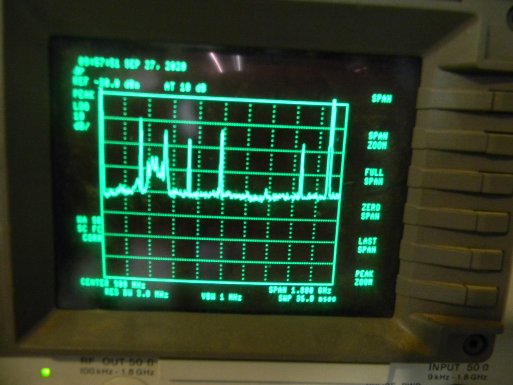
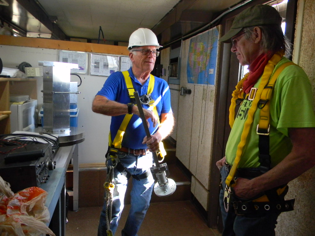
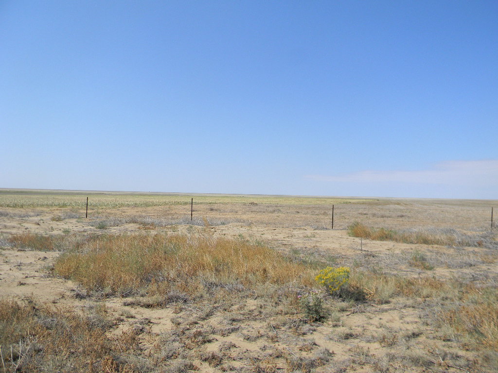
We kept the antenna steering in manual configuration. We opened the System 1 steering software to monitor the position angles as we manually steered the antenna to the service platform.We noted this radio interference at the site on our scope. This scan is from 0 to 1.8 GHz. The higher floor noise level at the left is from the sensitivity of our 408 MHz feed, which was still on the dish antenna, before we changed it out.The 60-foot antenna is positioned for service.Ray brought two feeds for the 60-foot antenna. This is Ray showing Floyd the 4 GHz feed, which we will use in the future, to calibrate the pointing position with geosynchronous satellites.Floyd carrying the 1296 MHz feed to the antenna for installation.The inside of the 1296 MHz feed. It is designed as a septum feed, with separate channels on each side for left and right circular polarization.Rob with a metal detector, crisscrossing the site, picking up small metal debris.Ray and Floyd on the 60-foot antenna service platform, starting work.Removing the cover.Ray is disconnecting the 408 MHz feed, so that it can rotate down and out for changeout.The 408 MHz feed is now rotated down. It is connected simply by the shaft to the mount, for easier changeout.Installing now the 1296 MHz feed. Its design doesn’t use a shaft, but instead will be securely fastened to the mounting frame.Ryan using a metal detector on the west side of the site.Our view towards the west. High clouds in the distance are an indication of a cold front gradually coming this way. We experienced steady windy conditions as the front approached..Closing up.Our view of Haswell in the distance. The clouds from the front were getting closer. By the time we left in mid-afternoon, the clouds were over us, but we had no precipitation.The 1296 MHz feed installed.We installed this ground mast. It will mount a small satellite antenna, to connect to the Hughes Internet network.
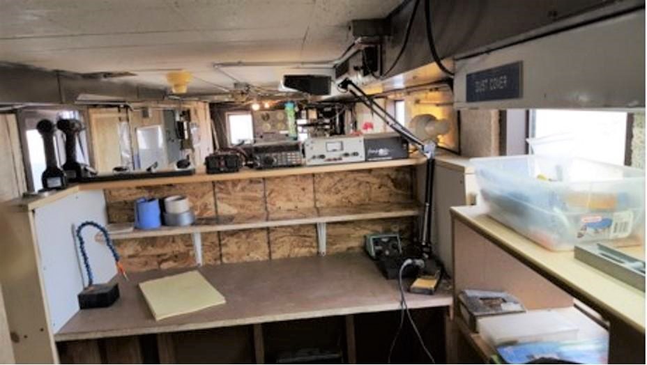
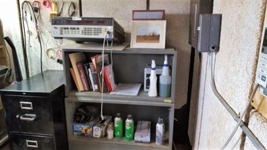
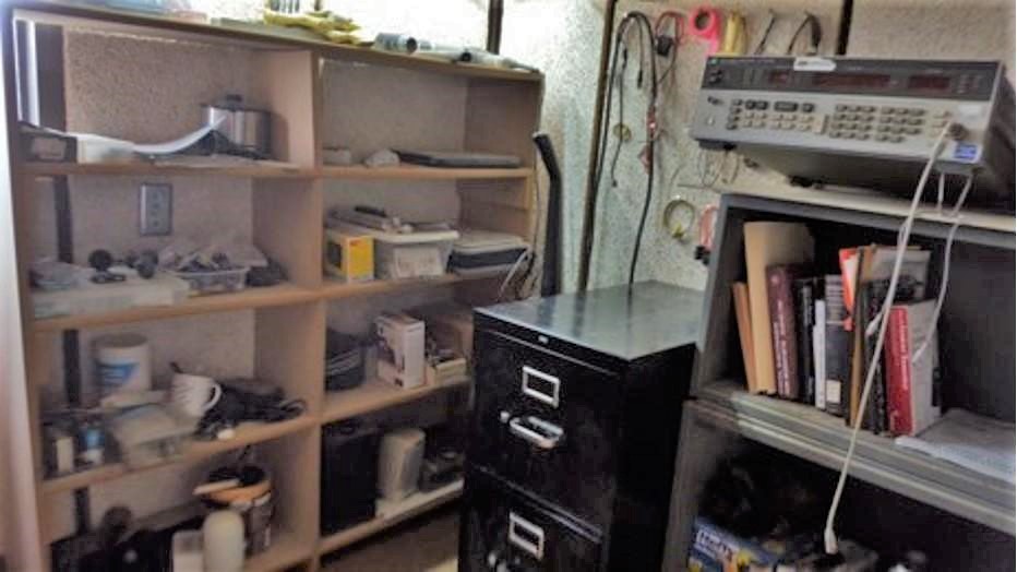
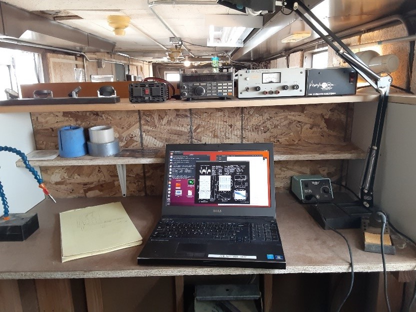
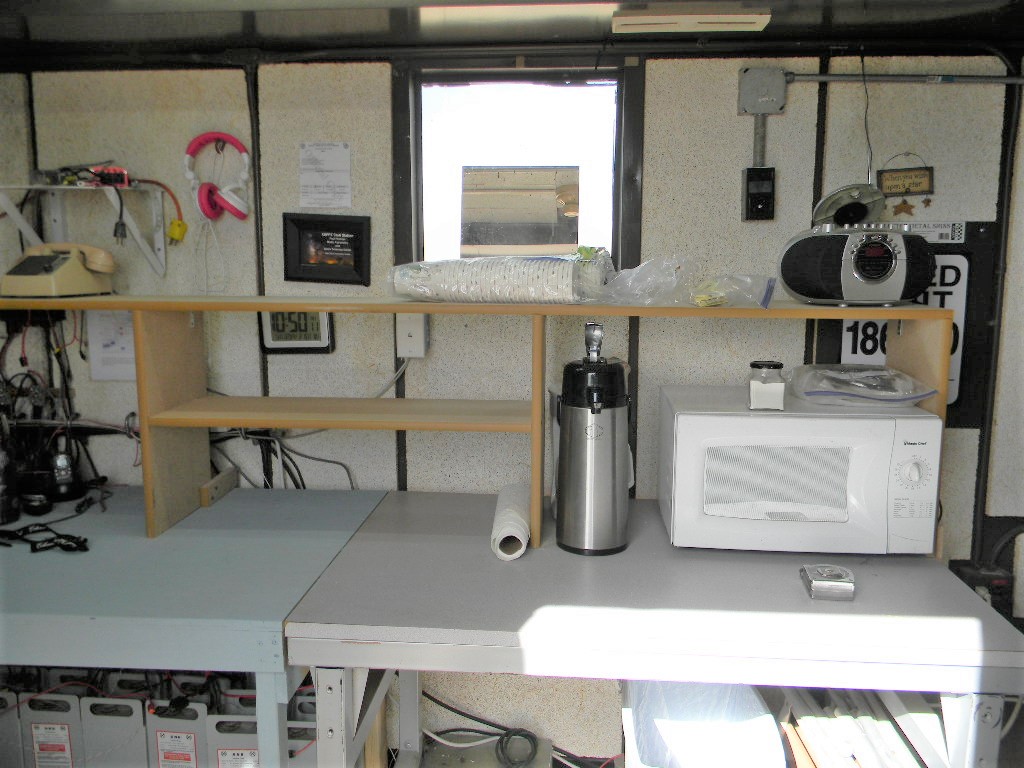
Bob Haggart (N0CTV) has been steadily improving the workspace of the science trailer at the Plishner radio telescope site. During the pulsar observation work on May 2, 2020, he completed building his latest enhancement: a partitioned work space at the east side of the science trailer. There is desktop space, which can be used for electronics building and testing. And there is additional shelf space, for better organization and storage.
Thank you Bob!
The new partitioned work area, seen from the middle of the science trailer.New desktop workspace, with room for building and testing. There is also close access to test equipment, references, and technical documentation.The work space in use during the pulsar observations on May 2, 2020.
I thought I would put out a System 1 status, so you can see what we’ve been working on the past couple of months.
To quickly summarize: Lewis Putnam has been concentrating on the System 1 hardware design (Please see the hardware diagram below) to support automatic tracking of the Haswell Mount.
Additionally he has been looking at the individual mount axis characteristics to see how well they can support sidereal tracking (See detail text below).
Phil Gage has supported myself looking at an Elevation axis movement issue we had seen at the site.
We found a loose cable on our March 1 trip which appeared to be causing the elevation axis issues.
Additionally, Phil has been working on the hardware/software interface for the Labjack hardware (Please see the hardware diagram below).
The Labjack hardware, the U3 and
JTick-DAC components, will be used to control the mount axis rates.
I have been updating the System 1 Hardware Simulator to support the Numato Relay Board and Labjack U3/JTick-DAC hardware devices.
Additionally, I’ve been working on the hardware/software interface to the Numato Relay board.
This device will be used to enable the drive controllers and control the direction of the Elevation Axis.
Using the work completed by Phil and the Simulator modifications, I’ve been able to test and debug most of the automatic tracking software modifications and simulate the System 1 tracking celestial objects over large periods of time (hours).
Here is a more detail summary of the past work and future work on the System 1 team (Before site modifications are performed, we will present our design work to the DSES Engineering Team):
March 12 2020 Trip
Purpose: Determine relationship between Az / El drive command voltages and rate resulting from command voltages
Approach:
Made measurements to calibrate mount Az and El drives (Rate as function of applied voltage)
Took measurements separately for Azimuth and Elevation
Measured both CW and CCW rates for Az and Up/Down rates for Elevation
Varied voltage via Trailer Control Panel Az and El rate potentiometers from 0 to 5 volts (.2-volt increments for voltages below a volt and 1-volt increments from 1 volt to 5 volts.)
Logged axis position data in System 1 software
Captured measurements in Excel spreadsheet and plotted
Findings:
Plotted results indicate linear relationship between voltage and rate for both positive and negative rates for both axes.
Performed linear fit to determine slope and intercept values that can be used to convert an axis rate into a command voltage.
Unique Slope and intercept parameters will be used in System 1 software
Slowest drive rates are .02 deg/sec for Az and .06 deg/sec for Elevation; lowest rates were consistent between positive and negative rates
Rates needed for sidereal track are about an order of magnitude lower
Will have to cycle axis drives on / off to achieve sidereal track rates
Elevation Potentiometer voltage will not go to zero
Lowest voltage is somewhat less than .2 volts
Cause is unknown but potentiometer is most likely candidate
Measurements for Elevation similar to results from August 2019 but measurements for Az significantly different from August results, unknown cause
Measurements in March were more extensive and disciplined. Will use calibration from these measurements in the implementation of the software.
System 1 Mount Drive Interface Hardware
Design/Implementation
Progress:
Completed hardware circuit design
Interfaces to the tower drive electronics via the Jones Plug
Uses a Labjack U3 device / TickDAC that provides two +-10-volt Digital Analog Convertors to enable setting Az / El axes control voltages
Labjack has necessary digital I/O to interface to the axes encoders so downstream can be used to replace the now obsolete Integrity Systems digital I/O board
Uses Numato 8 Relay Board to enable the drive controllers and control direction in the Elevation Axis
Developed an approach to integrating circuit into the trailer rack
Mount components on a small rack shelf about 6” deep
Mount shelf on back rails of the Trailer Rack
Move Jones cable from Manual control panel to System 1 Drive Control when using System 1 for drive control
Acquired major components and some minor components – Numato 8 Relay Board, Labjack interface device, Jones plug and wire
Participants: Rich Russel, Bob Haggart, Glenn Davis, Lewis Putnam, Bill Miller, and Gary Agranat.
Photos by Bill Miller and Gary Agranat.
We worked at the Plishner antenna site in Haswell on Saturday February 15, 2020. We had three projects:
Attempt at observing a circumpolar pulsar, utilizing the System 1 manual tracking system. (Rich Russel, Glenn Davis, Lewis Putnam).
Complete building and installing shelf space in the Communications (Operations) Trailer (Bob Haggard).
Repair of the 3-element Yagi ham radio antenna, to realign the three elements (Gary Agranat, Bill Miller, Bob Haggard).
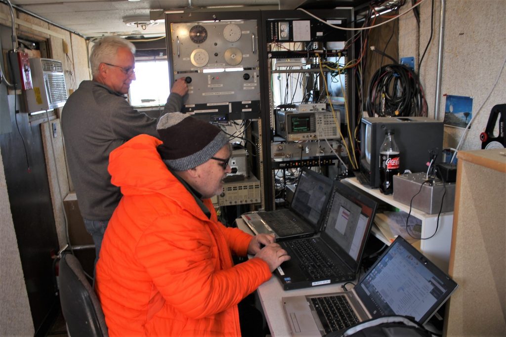
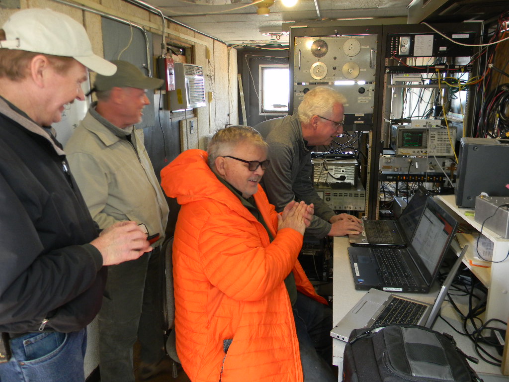
1. The major task of the day was an attempt at a science observing run of a circumpolar pulsar. This is one of the brighter puslars in the sky. And being circumpolar, it is always above the horizon, though it can still get relatively low to the horizon. The observing technique required continually pointing a the celestial coordinates and integrating the signal for at least a half hour. By integrating over time, the random noise tends to cancel more, leaving the actual radio source signal the time to accumulate and sum to a higher level than the noise floor.
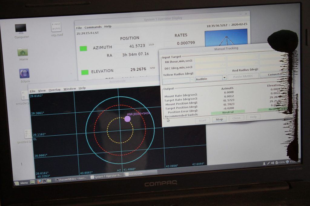
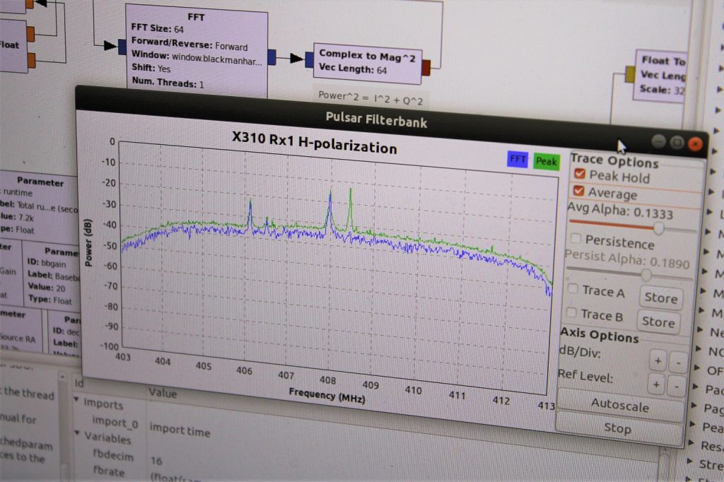
Science Lead Rich Russel (seated) and System 1 Lead Glenn Davis setting up the pulsar observations. Bill Miller, Lewis Putnam, Rich Russel, and Glenn Davis in the Communications Operations Trailer during the observation runs.The display for the System 1 manual tracking. The circles in the black field represent the antenna beam width for different frequencies. The large blue ring represents a 4 degree diameter beam width, and is for the 408 MHz feed currently being used for the pulsar observing. The inner yellow ring is 0.8 degrees in diameter, which is for our HI hydrogen observing at 1.4 GHz. The pink dot represents where the center of the beam is pointing. A star field map is projected on the background black field. The upper part of the display shows azimuth and elevation of the antenna, and its conversion to the celestial coordinates of Right Ascension and Declination at the current time.The signal strength across the frequency spectrum being observed. For pulsar observing, we cannot detect the pulsar signal itself in real time. We must integrate the signal over at least a half hour of observing. Then we process the signal, with an expected pulsar timing. That process averages out the background noise while adding the actual pulsar signal enough to elevate above the noise floor — in theory. The 60 foot dish antenna turning to aim at the pulsar.The 408 MHz antenna feed. Ray Unberecken has designed a base for the antenna feeds so that these can be easily swiveled out for service and changeout. Ray designed and built this feed.
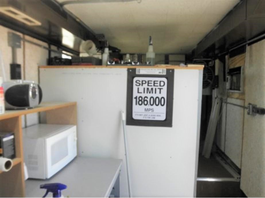
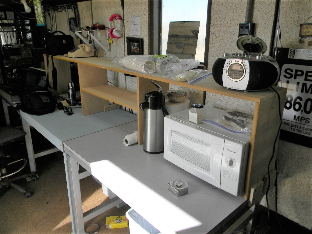
2. Bob Haggart worked on completing the building of desk and shelf space in the Communications Operations Trailer. The additional space is actually important, as that gives us a means to organize and better utilize our work space, and not instead have items pile up randomly.
Bob HaggartNew desk and shelf space in the Communications Operations Trailer.New desk and shelf space in the Communications Operations Trailer. Note the addition of amenities, of microwave oven and coffee pots.
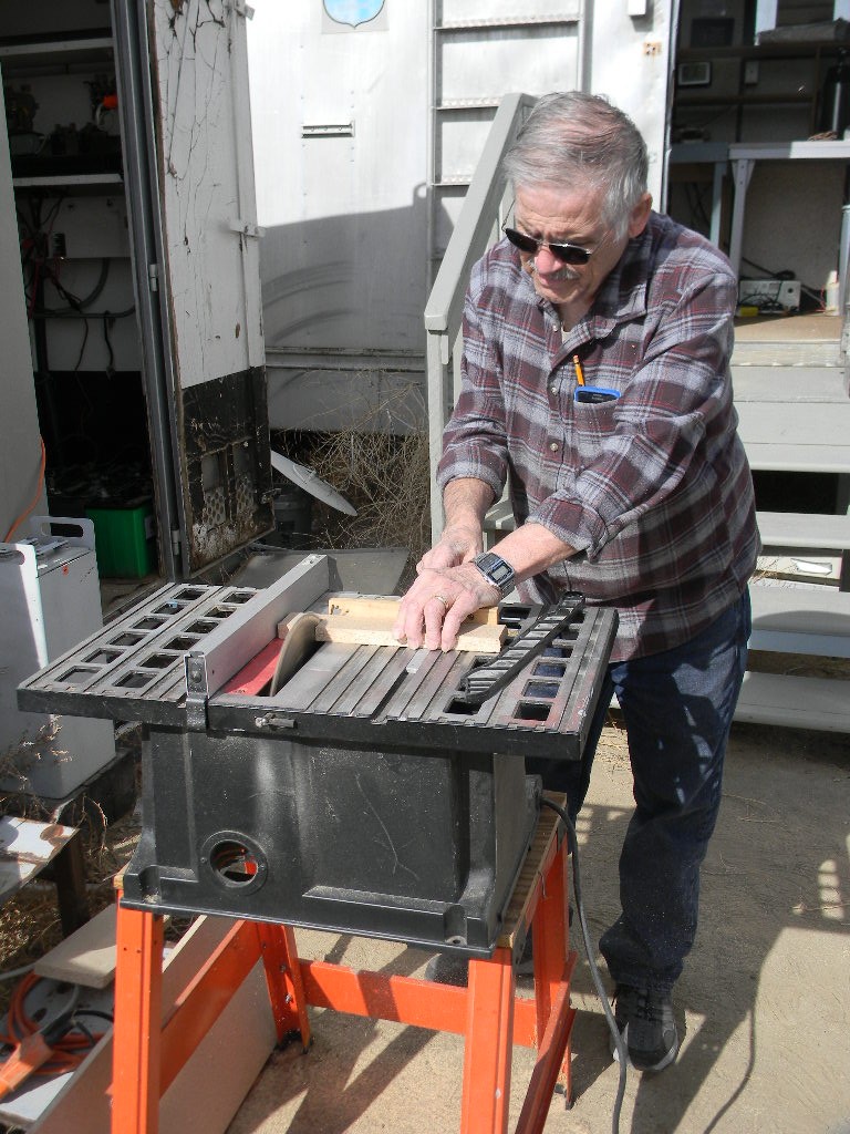
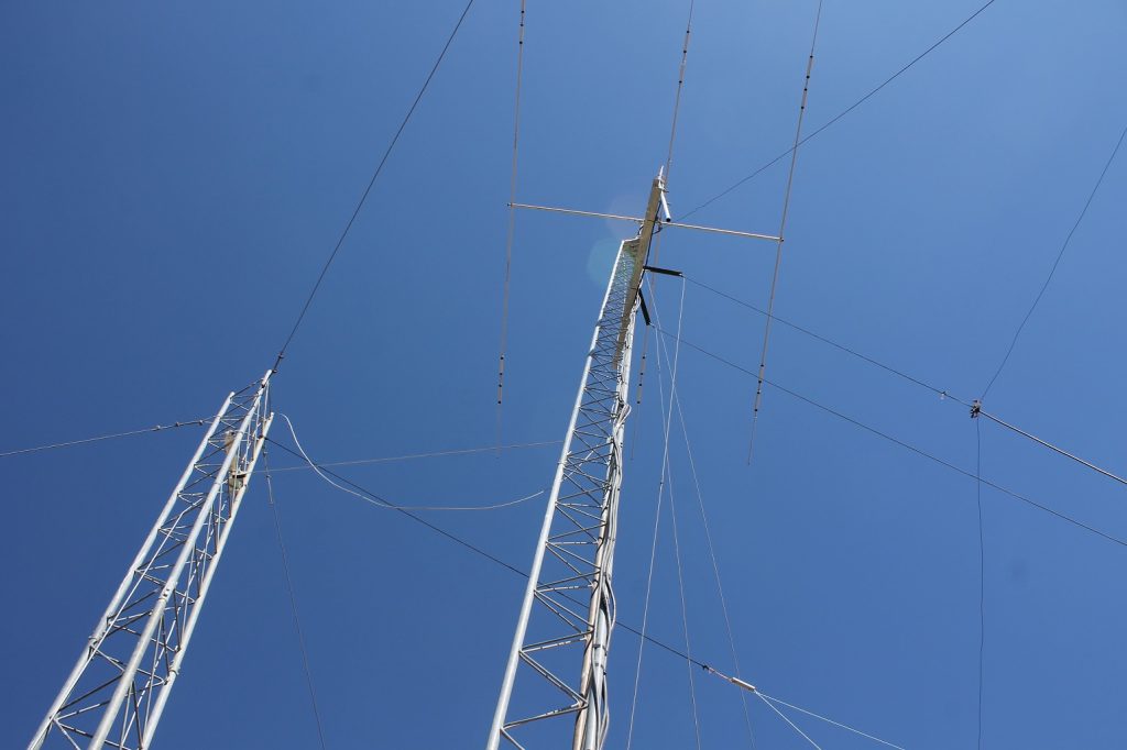
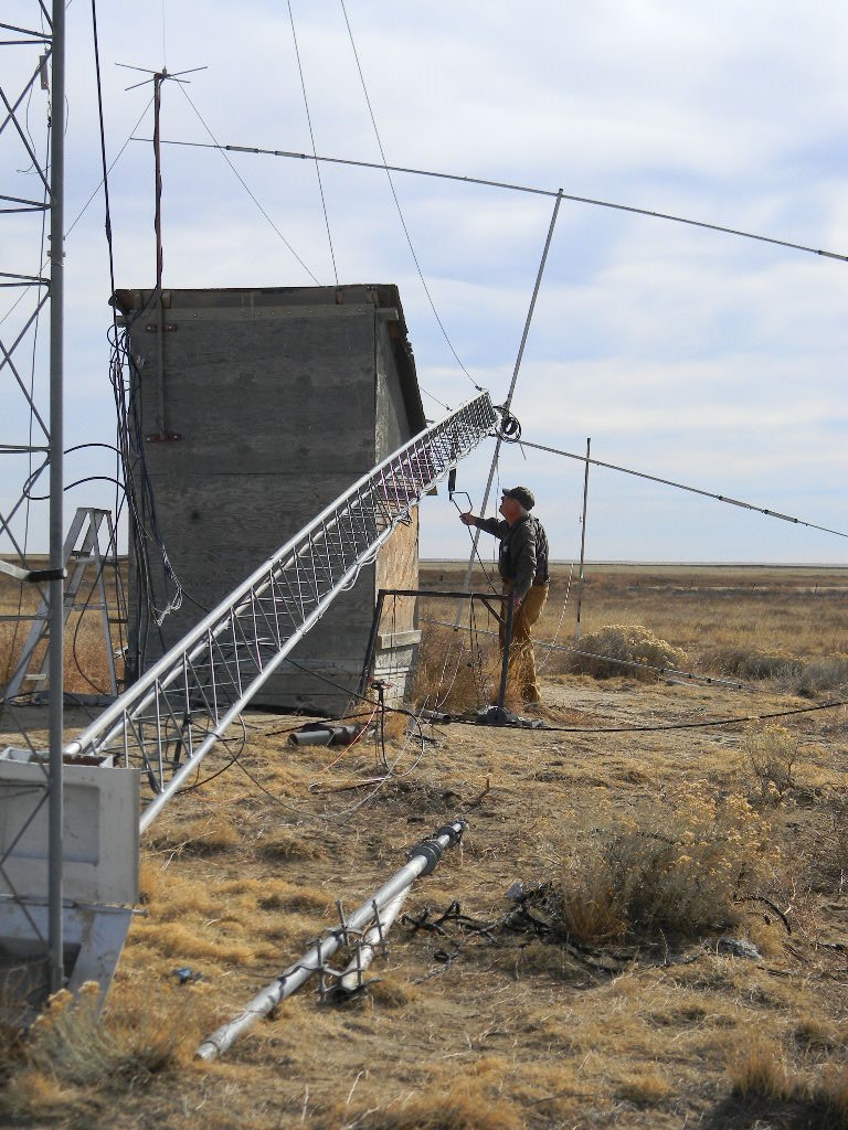
3. A third project was the repair of the front element of the 3-band Yagi ham radio antenna on the 40-foot tower. The front element had rotated slightly askew.
The front element of the 3-band Yagi ham radio antenna on the 40-foot tower rotated askew somehow. Fixing this was our third project undertaken this day.The tower was rotated down for service.Bill Miller aligning the front element. Also working on this were Gary and Bob. Bob utilized cable lengths to help ensure actual evenness. We also used squares and levels. Gary working on the antenna. The ladder was used to access and retighten the center supports at the mast. While the tower was down for the service, Bill reinforced the structural support for the 2-meter band vertical antenna on a side support from the tower.Gary raised the tower back up.The 50-foot tower almost at its vertical position.
After the tower was raised back to vertical position, Bill and Gary slightly rearranged the positioning of the 80 meter dipole that is supported from a pulley on the tower. The repositioning separated the dipole with better clearance from other nearby wires
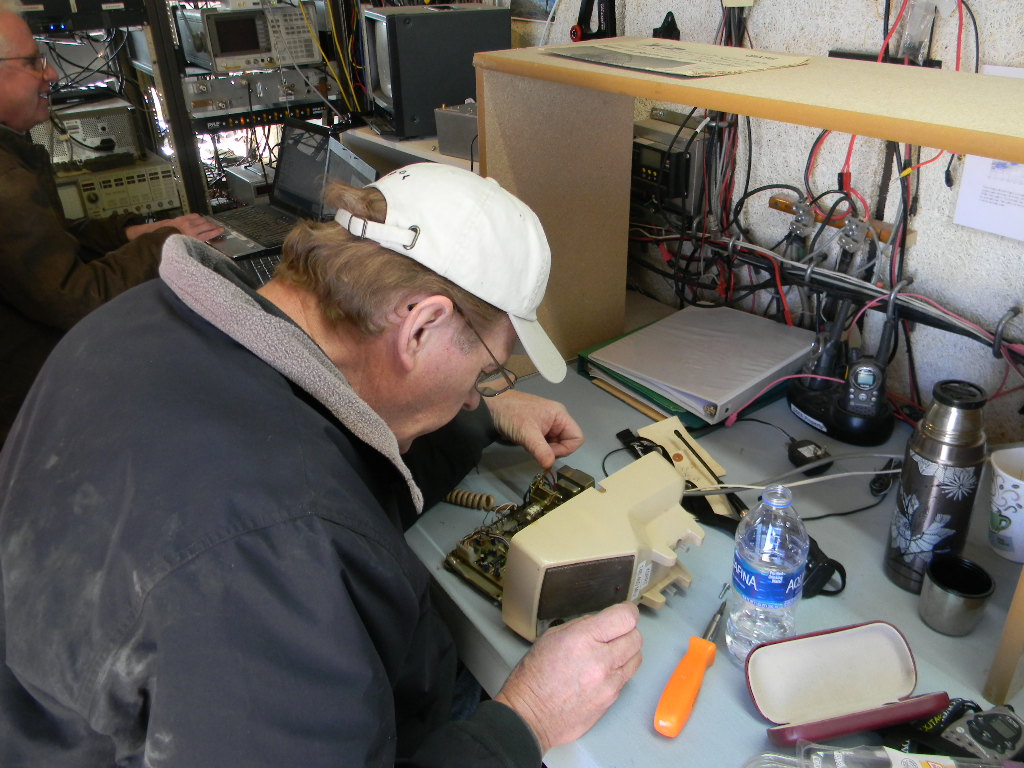
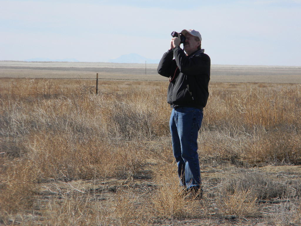
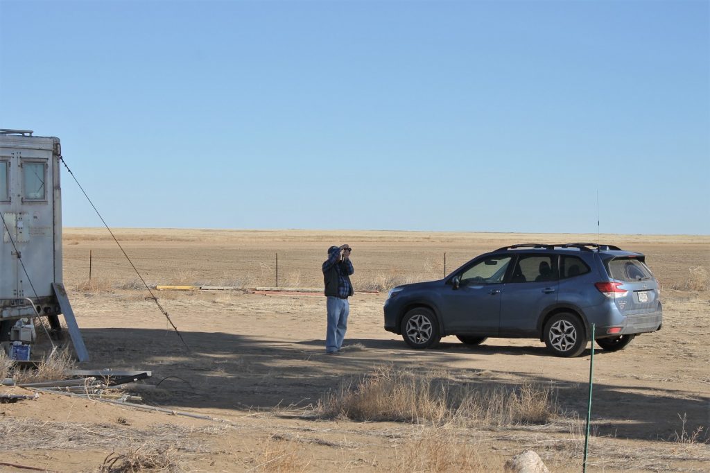
We discovered that the Communications Trailer phone used for our 2-meter talk-in radio was transmitting but not receiving. Bill started to troubleshoot it.Bill photographing the dish antenna. Pikes Peak is visible in the distance, over a hundred miles away.Gary also photographed the dish antenna.The 60 foot antenna rotating back to its parking position after the observing runs.
Rich Russel processed the observation data, but the processing did not bring out the pulsar. Troubleshooting is a topic at the February Science Meeting. Meanwhile, the System 1 antenna pointing system worked well.
The group finished up the work well before sunset, so that traveling back with the sun setting was not a significant issue. We had good weather for this trip, for a winter day in February. Our temperature was in the 40s F, which was actually midler than the 30s in Colorado Springs. And our wind was light.
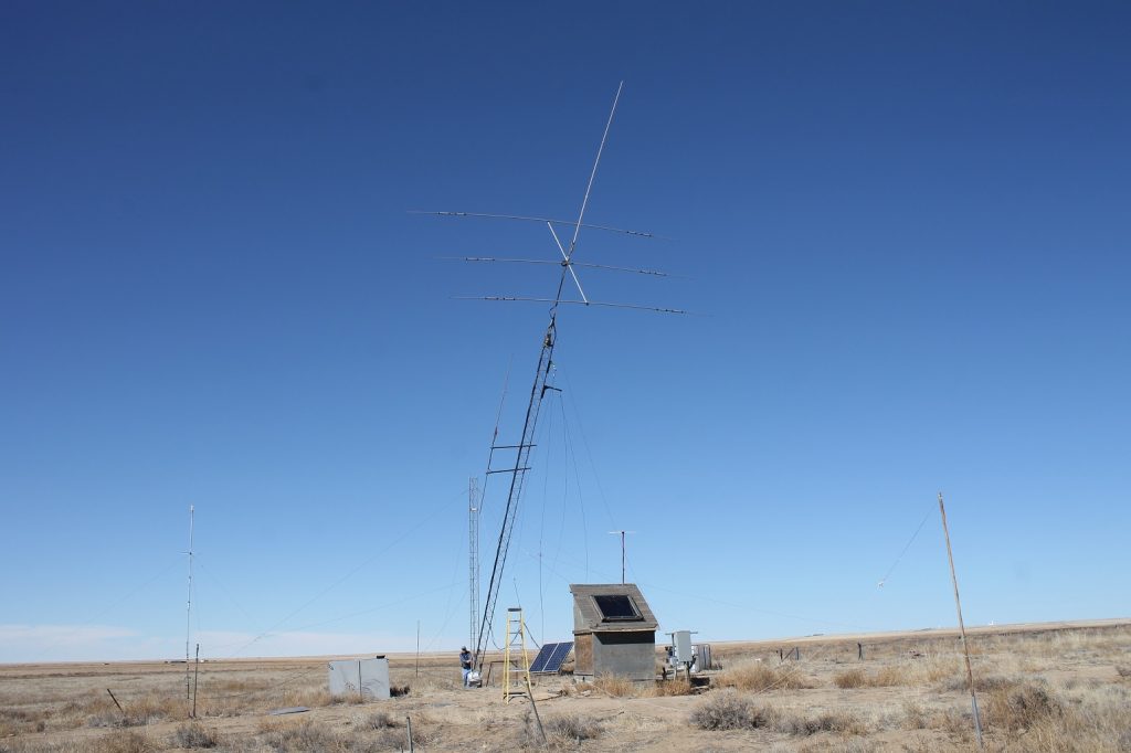
As we do each third weekend of the month, we had a scheduled work day at our DSES Plishner radio astronomy antenna site in Haswell, Colorado. Our members who participated on this weekend were Steve Plock, Ed Corn, Ray Uberecken, and Gary Agranat. Work objectives were:
Completion of installing the antennas and cables on the new 50 foot ham radio antenna tower.
Servicing the 60-foot dish antenna feed.
We typically meet first at the Ellicott firehouse for carpooling, before heading to the Plishner site.
I will save discussion of the 60-foot antenna feed for the Engineering Meeting minutes. That work was done by Steve Plock and Ray Uberecken. In this post I will describe the work we completed for the 50 foot tower.
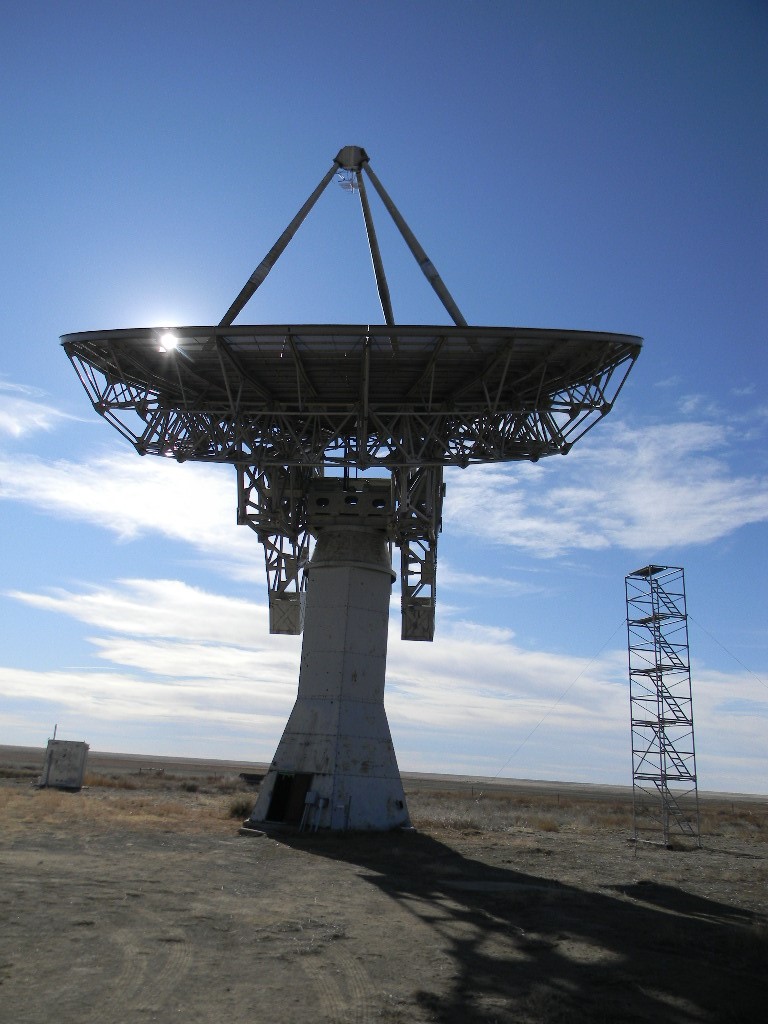
The 60-foot dish antenna was rotated to the service tower, to enable Steve to work at the feed point.
With the 60 foot dish antenna rotated to the service tower, Steve worked at the antenna feed.
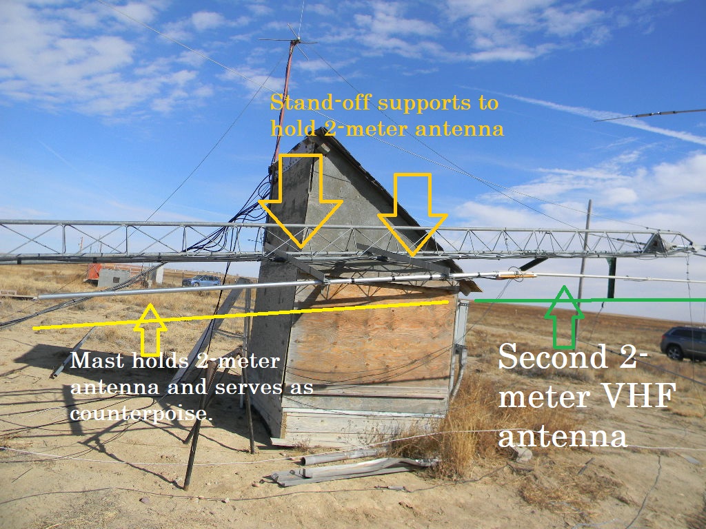
For our 50-foot tower work, we installed a second vertical antenna for normal contacts on the 2-meter VHF band. This gives us a second 2-meter band capability, independent of our already existing 2-meter band talk-in radio. We then installed coax cables for both of the 2 meter band antennas on the tower.
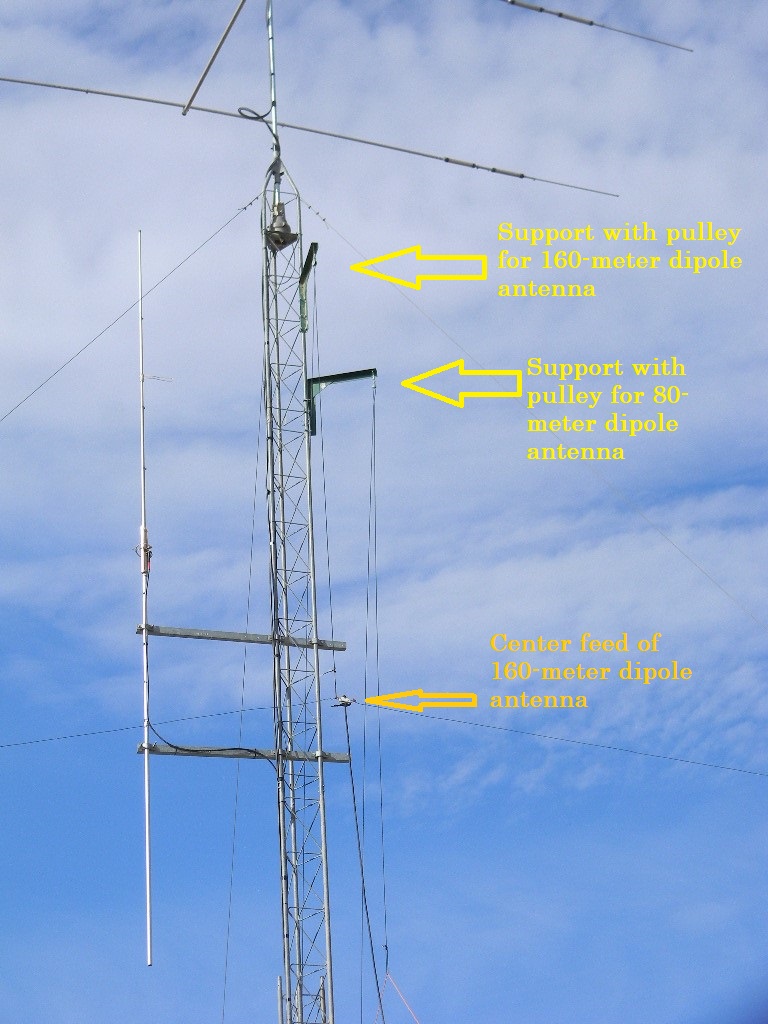
We also serviced the 80 and 160 meter band dipole antennas that the tower supports: 1) We replaced some of the nylon rope that lifts the dipole antennas to their deployed positions. Previously we had connected shorter pieces of rope and knotted those together. But the knots stuck in the pulleys, and we therefore replaced those with longer sections of rope without knots. 2) We neatened the arrangement of the wire antennas supported by the tower.
Captions to the photos provide more detials of the work.
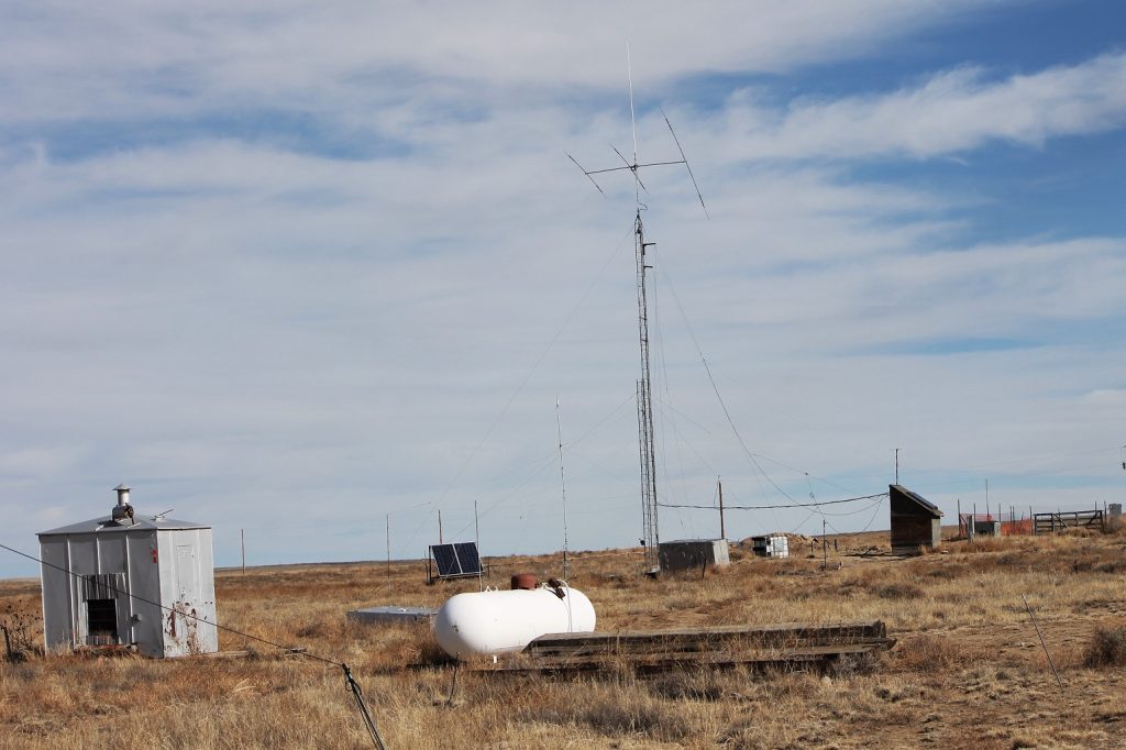
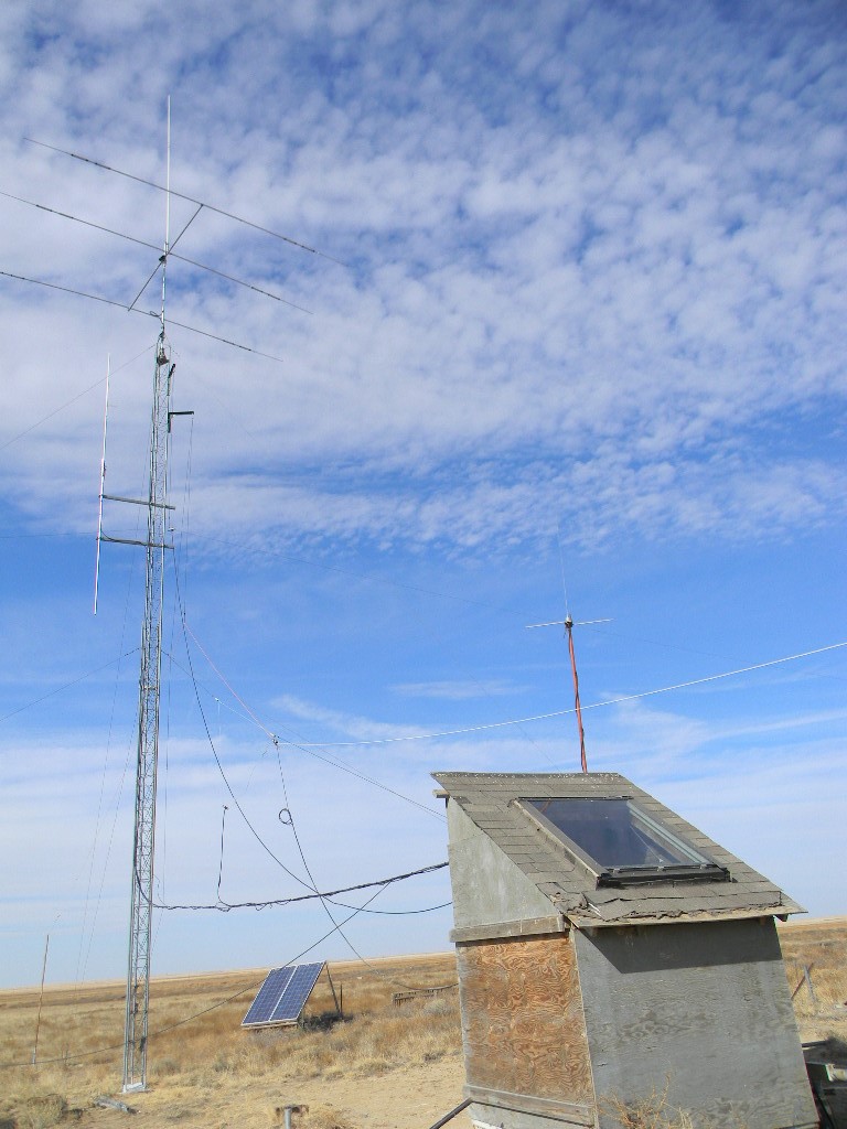
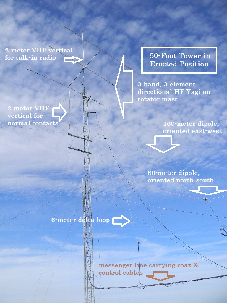
Ed and Gary lowered the 50-foot ham radio tower. A second VHF 2-meter band vertical antenna was added to the side of the tower, in addition to the VHF talk-in radio antenna placed last month at the top of the tower. And coax cables were added that feed both VHF antennas.The second VHF 2-meter band antenna was added here, at this upper location along the side of the tower. Two stand-off support arms were bolted to the tower. Then the antenna was connected to its mast, which fits from below as a sleeve fitting. And the mast was connected to the supports. The mast serves both for structural support and as a counterpoise. The tower raised up again.The tower supports these ham radio antennas.The tower supports the 160 meter band and 80 meter band dipole antennas by rope and pulley systems. The 160 meter antenna is oriented east-west, and the 80 meter antenna is oriented perpendicularly north-south.Ed’s work truck on site.
After we serviced the ham and radio astronomy antennas, Steve made us lunch by smoking beef sausage in the grill. That was served with coleslaw and potato salad. Gary also brewed coffee.
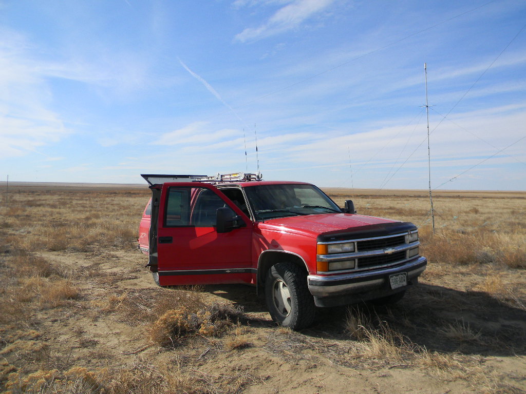
After the tower was raise back up, Gary operated on phone and FT8, using the tri-band Yagi on 15 and 20 meters, and using the 80 and 160 meter dipoles. (10 meters was tried also but with no results, likely due to the poor propagation conditions.) The operating was in part for fun, and in part to verify that the antennas we put back up functioned properly. They all functioned well.
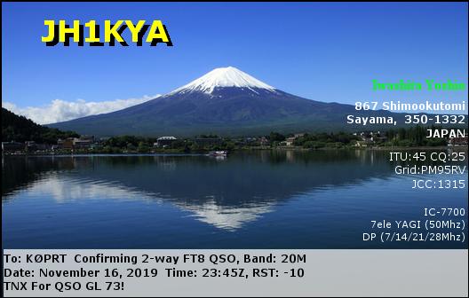
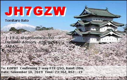
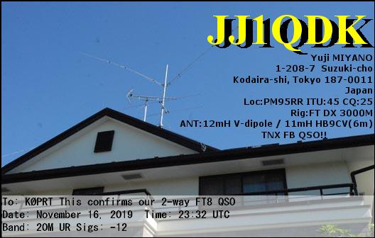
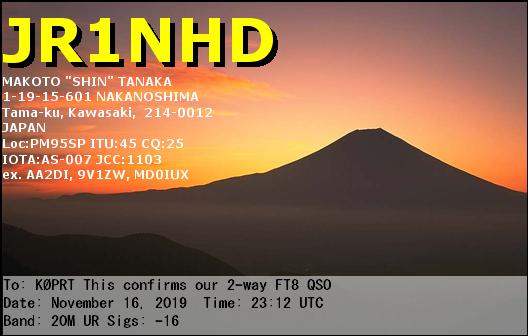
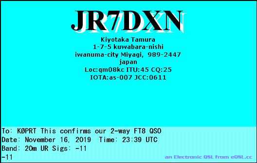
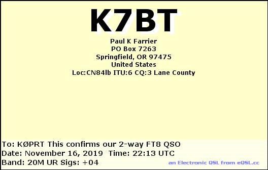
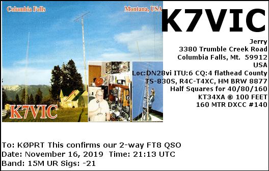
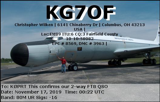
After lunch I did some ham radio operating using the tri-band Yagi, and also the using the 80 and 160 meter dipoles. With the tri-bander, I first made a phone contact to Hawaii on 15 meters, before the bands got busy with the ARRL sweepstakes. Then I operated FT8: on 15 meters I mostly contacted South American stations (lots of Brazil), plus some US stations when they were there (including North Carolina and Montana). On 20 meters the band opened across the Pacific. We had many calls to us from Japan. Perhaps they saw our profile on QRZ, or perhaps they noticed our rare grid square. Also across the Pacific, we made two contacts with South Korea, one with mainland China, one with Indonesia, and one with Australia. The band became weaker for US and Canadian contacts, but we did have some of those too. I alternated going to 80 meters, and had a few more domestic contacts there. These were with our K0PRT station callsign. Later I also used my callsign, on 20, 80, and 160 meters. 160 meters had noise at the FT8 frequencies. But I went to the upper portion of that section of the band, which was just slightly better. I managed 4 contacts on 160 meters, to as far away as Kentucky. I would say our antennas were working well.
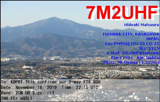
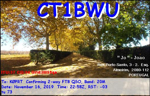
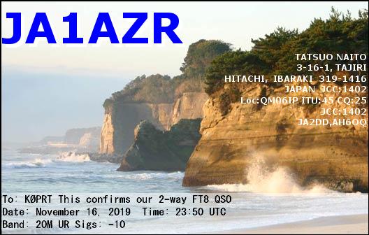
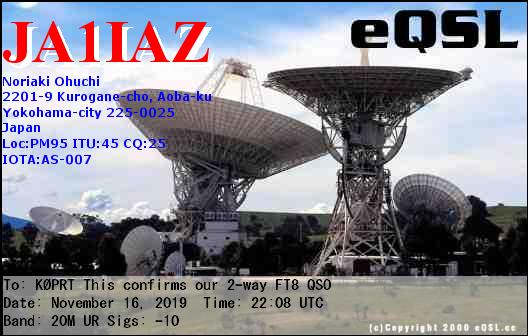
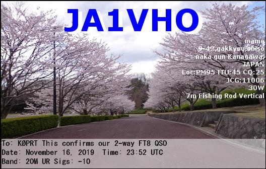
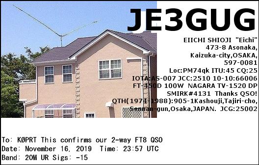
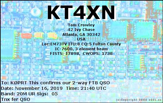
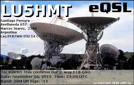
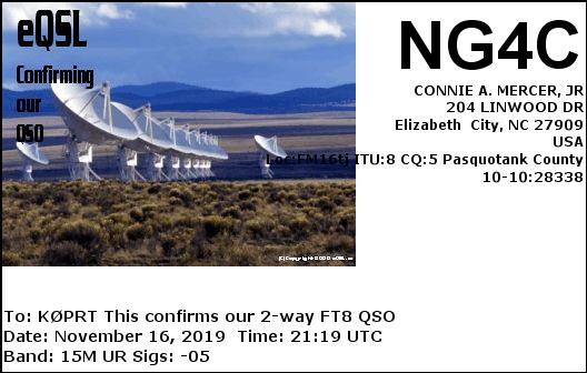
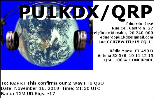
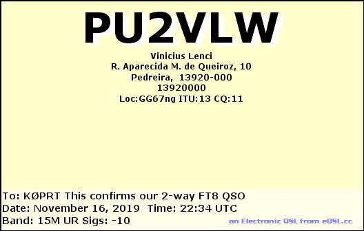
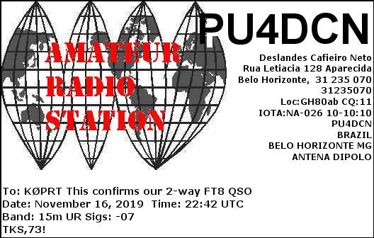
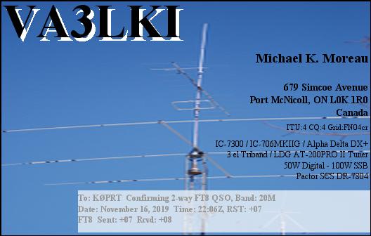
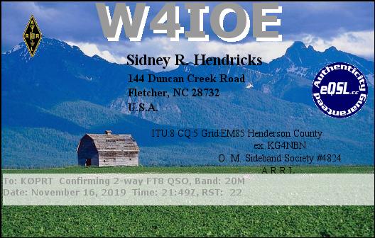
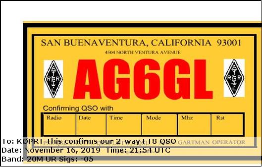
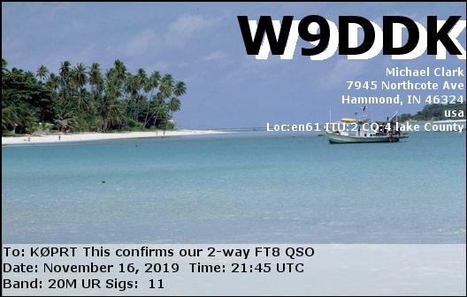
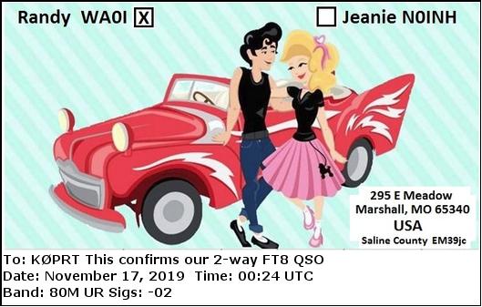
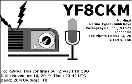
Within a few days we received a number of e QSL confirmation cards.
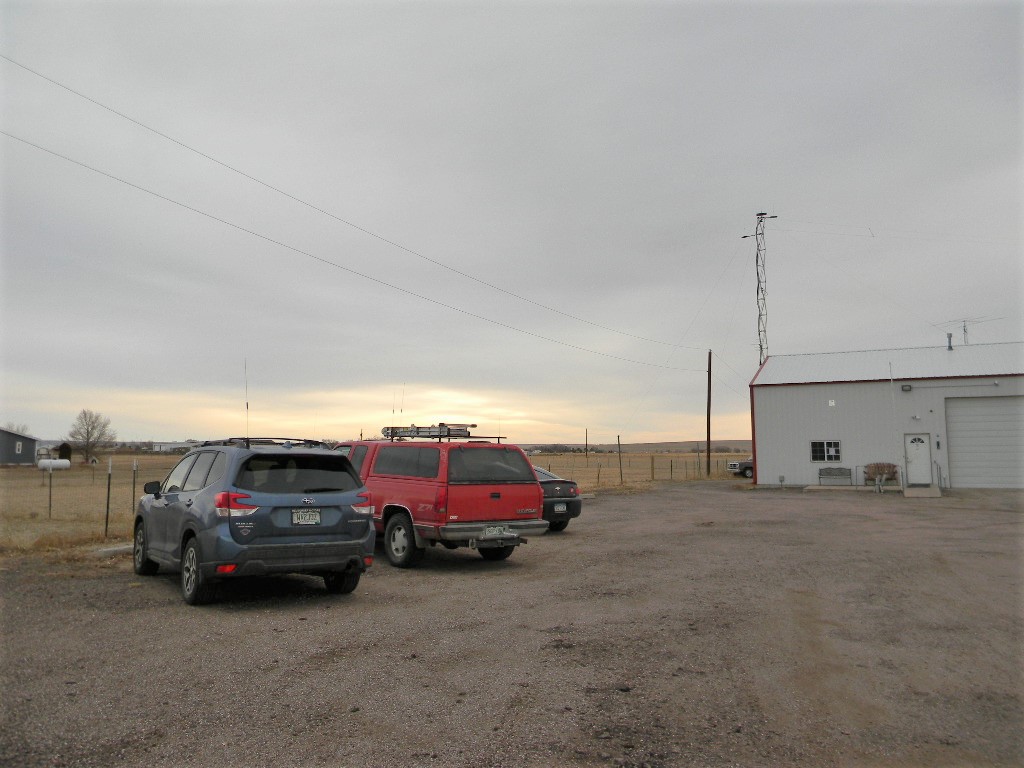
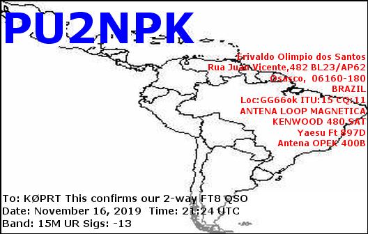
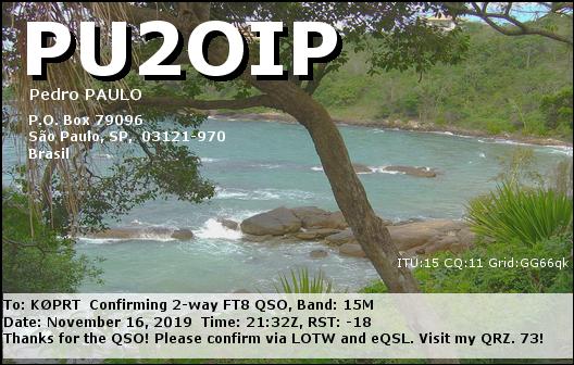
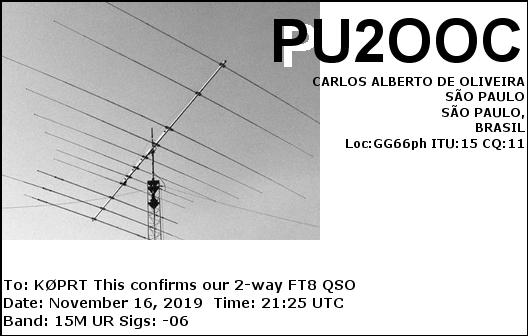
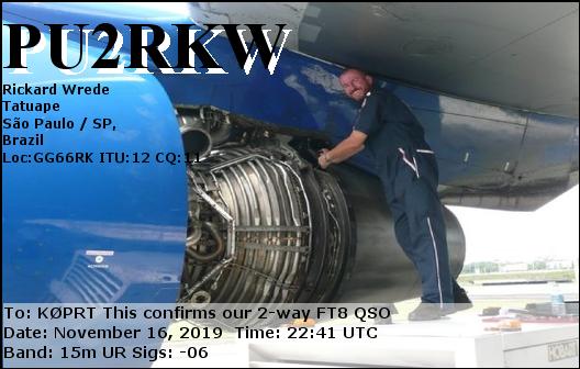
eQSL cards we received from our contacts. The callsigns starting with J and 7M are in Japan. The ones starting with PU are in Brazil. LU5 is in Argentina. CT1 is in Portugal. YF8 is in Indonesia. VA3 is in Ontario, Canada. The other callsigns are in the United States.The site at the end of the day.
Ray left after lunch. Ed and Steve left before sunset. Steve tested the range of the new talk in radio antenna on the tower as he and Ed drove home away from the site. We had good contact to as far away as Sugar City. At JRs in Ordway, we could hear each other, but Steve needed to turn off his squelch. And at that point there were some slight dropouts. But we could still communicate. That is a great improvement for our talk-in system. Gary stayed and operated the ham station until a little after dark, and then closed up and departed too.