Our System 1 team members are Glenn Davis, Lewis Putnam and Phil Gage KI0NY.
Manual Steering
Documentation for this will be added soon.
Original Steering Controller
The old System 1 Startup/Execution/Shutdown Procedures are described in the following documents.
New Steering Controller
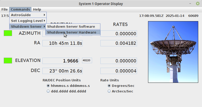
This document discusses, at a high-level, the startup and shutdown steps for the new System 1 software (Version 9) which uses the new 16-bit encoders.
Technical Information
The following information was provided by Glen Davis on 19-Nov-2025.
Azimuth and Elevation Calculations
Let me explain how we calculate the Azimuth and Elevation position data displayed on the System 1 main menu. The encoders are 16 bits in width, so the range of values for both encoders is 0 – 65535 counts. Therefore, each encoder position is 360.0/65535 = 0.0054932 degrees from the next encoder position. Using this constant and what I call the “Zero Crossing” initialization value, we can calculate the Azimuth and Elevation positions. The “Zero Crossing” value is the encoder value that is reported by the system when an axis is at 0.0 degrees. In the current system, at the site, the Azimuth “Zero Crossing” value is 33068, and the Elevation “Zero Crossing” value is 48578. Using the currently reported encoder position and the “Zero Crossing” value, you can calculate the current axis position in degrees.
So, this calculation would look something like this: Current Axis Position = 0.0 + (( Reported Encoder Position – Zero Crossing Value) * (360.0/65535)). This is a slight simplification of what the software does due to “special cases” such as encoders rotating in the opposite direction of their axis, or the range of motion of the axis.
To help us determine the correct “Zero Crossing” position for each axis, we developed a Mount Calibration command that determines the current pointing errors in the system. Using known radio sources as calibration positions, we scan around the calibration position to determine the error in each axis (known position vs. reported position). We then update the software initialization file with the modified “Zero Crossing” values to negate the pointing errors. Hopefully, this helps you understand how we calculate Az/El position data for each of the axes
Auto slew/tracking capabilities
First, let me describe the use of the J2000 Coordinate System in the System 1 software. All star and planetary display data and object position calculations are done using the Right Ascension and Declination J2000 coordinate system. J2000 is a fixed celestial coordinate system based on the mean equinox of the year 2000. The J2000 system provides a stable, fixed reference for cataloging positions (from Google). However, to be able to point at a celestial object at the current time (current epoch), the J2000 RaDec position has to be converted to an Apparent RaDec position. An Apparent Position is the actual location of an object as seen from Earth’s surface at the current time. To determine the Apparent Position, the J2000 position is corrected for effects like Earth’s procession and nutation, annual aberration, and light travel time. So … in the System 1 software, for any type of object we wish to track, the software calculates a J2000 RaDec position. This position is then converted to an Apparent Position, which is converted to an Azimuth/Elevation Position. The Az/El Position is used to command the mount.
I only bring up J2000 Position vs. Apparent Position because you have to be careful when comparing two Ra/Dec positions (apples to apples comparison) or when you command System 1 using a Ra/Dec position. You have to use J2000 RaDec coordinates when commanding System1. Typically, planetarium programs and online programs can display the current RaDec object position in either J2000 or Apparent. Always use the J2000 position data to command the mount.
Now, a discussion on how the mount tracks an object. Since we can’t command the mount to sidereal rates (the mount doesn’t support slow rates), the software has to calculate the object position, slew to the calculated position, then the mount settles at that position and waits until the object position error is greater than a threshold value. When the threshold is exceeded, the mount is commanded to its newly calculated position. This is repeated until the Track Commanded is canceled. We have propagation software (position calculators) that determines Sun Position, Moon Position, Planetary Position (except Pluto), and Deep Space (Geosynchronous) Satellite Position data, all in the J2000 coordinate system. To calculate the position of a Geosynchronous satellite, we use the SGP4 propagator algorithm. The SGP4 propagator is an algorithm used to calculate the position and velocity of Earth-orbiting satellites based on the two-line element (TLE) set. TLEs are available online. System 1 will automatically download the latest TLE when requested.
So, to answer your second question. Deep Space objects such as Voyager and New Horizon spacecraft are essentially stellar objects. Their Ra/Dec values change very slowly over time. So, if you can find a J2000 RaDec position for these two objects, you can use the System 1 Ra/Dec Automatic Track command to track these objects. The J2000 Ra/Dec positions for these objects can be found on the “The Sky Live” website. For the other objects in the list, since I don’t know their apparent rates, I’m not entirely sure how you can track them using the System 1 software. If the rates for these objects aren’t too terribly large, you could track them using the same method I described above for the Voyager spacecraft. Instead of letting the command run open-ended, you could cancel the Track Command after a calculated time (based on object rates), then reissue the same command using the current J2000 RaDec position. This would manually bump the antenna along with the object.