Plishner Work Trip Report – August 24, 2019

By Gary Agranat

Participants: Ed Corn, Steve Plock, Gary Agranat.

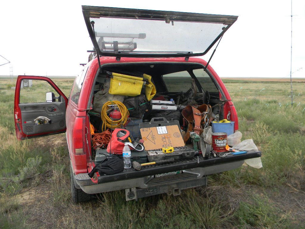
Ed, Steve, and I traveled to our radio telescope site, leaving from the Ellicott Fire Department a little after 7:30 am. We encountered just a little fog on the way.

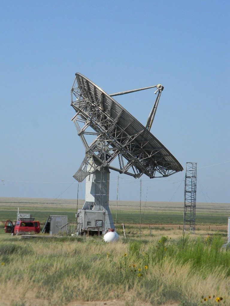
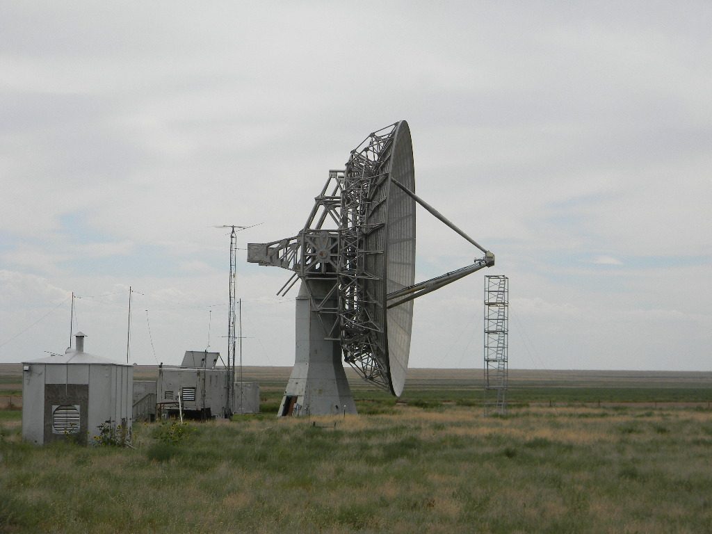
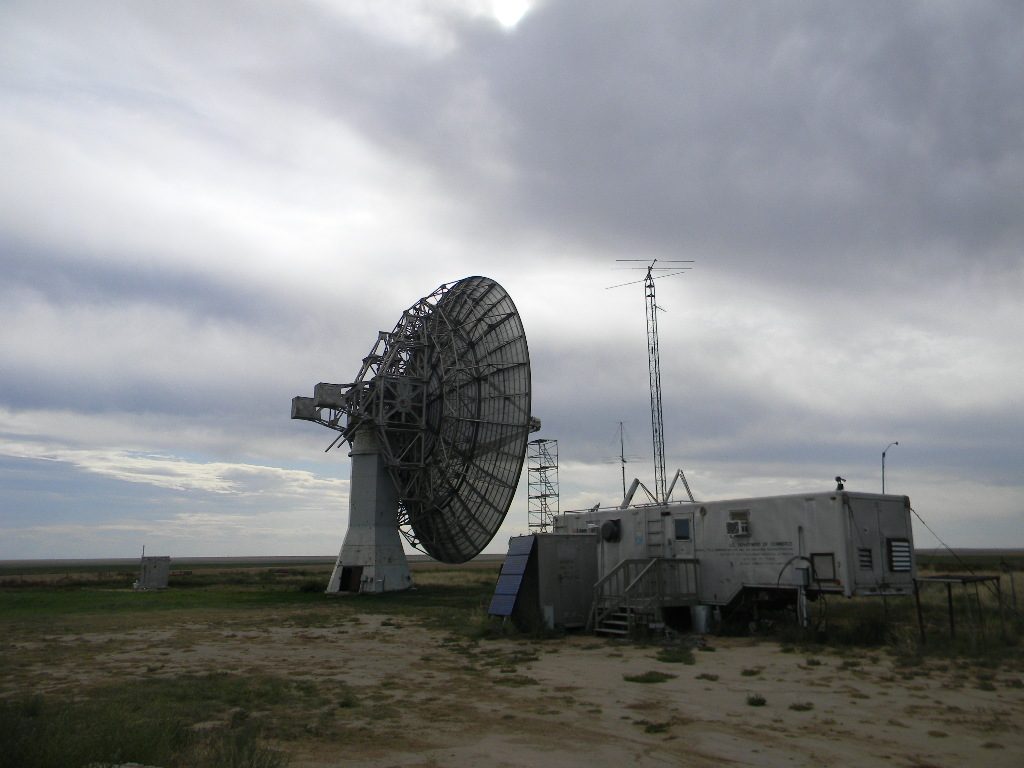
Steve worked primarily on troubleshooting the amplifier failure on the 60-foot antenna fiber optic feed. Steve found a power supply no longer functioned. He wrote me later, “Damaged parts have been ordered and will be replaced at the earliest convenience.”

The 60-foot antenna dish was rotated so that Steve could access the feed from the service tower.

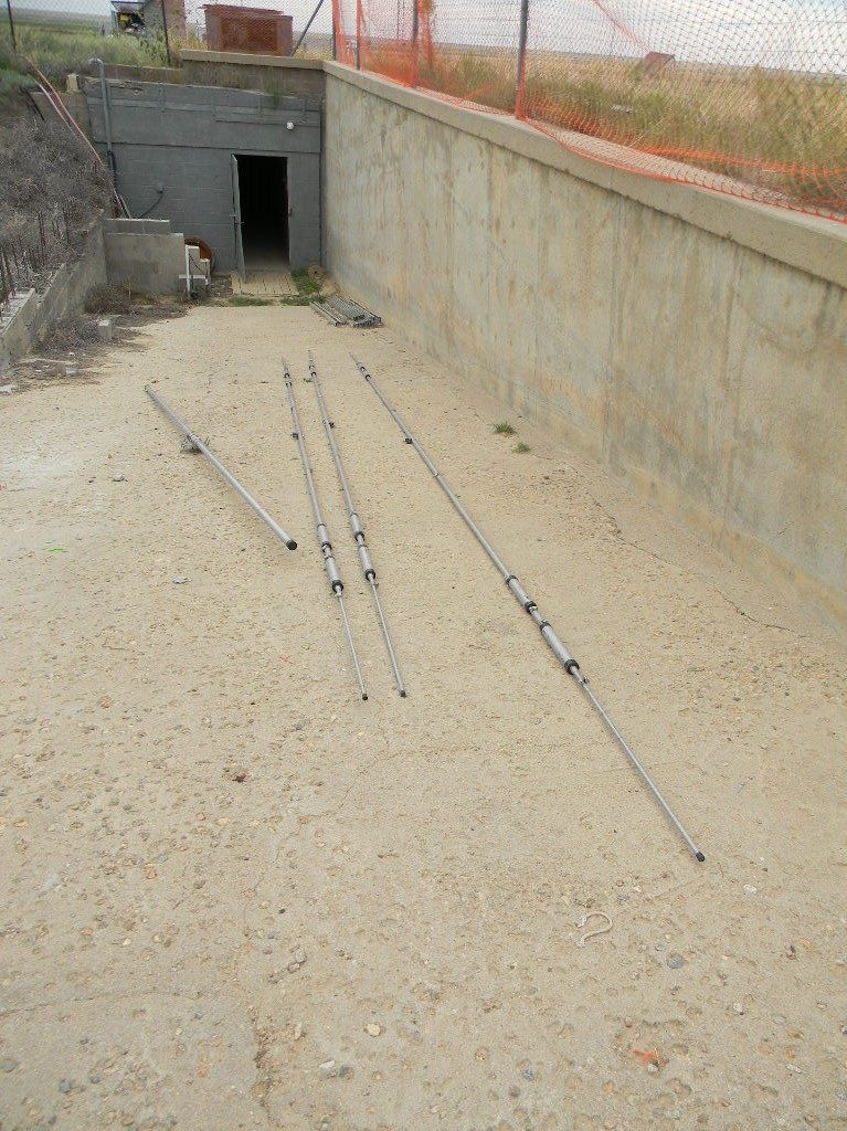
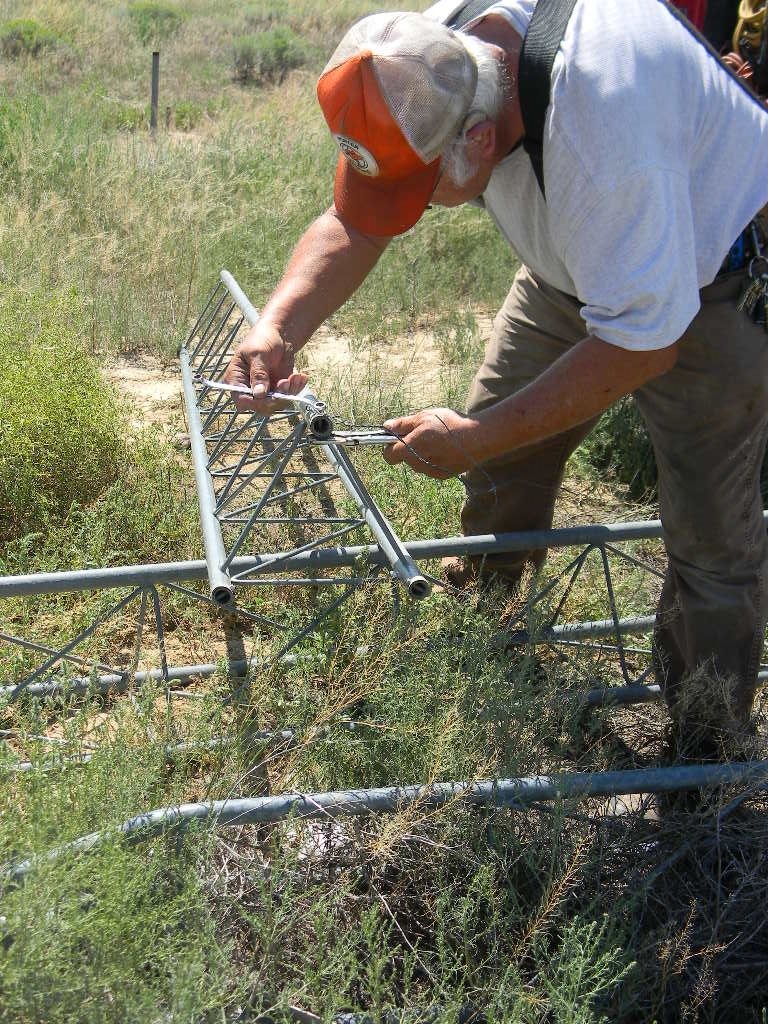
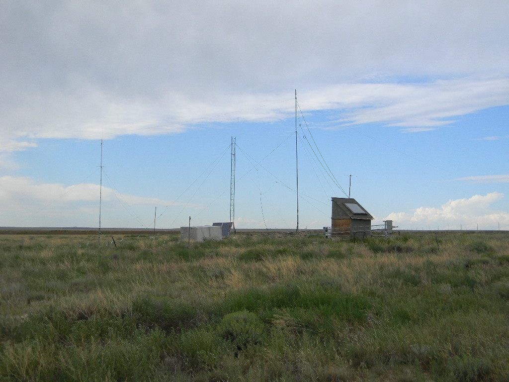
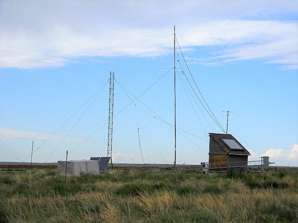
Ed Corn and I worked on assembling the 3-element tri-band Yagi antenna from Myron Babcock, and then the ham radio tower by the bunker, on which the Yagi antenna will go.  We measured and reassembled the three Yagi antenna elements and the boom support for them.  We’ll wait to combine those until we are ready to attach the antenna to a mast and on to the tower.  The antenna will operate on the ham 10, 15, and 20 meter bands. We decided to set the lengths so that the antenna tunes best in the center portions of the bands.

Assembly of the three elements of the tri-band Yagi antenna and its supporting boom.

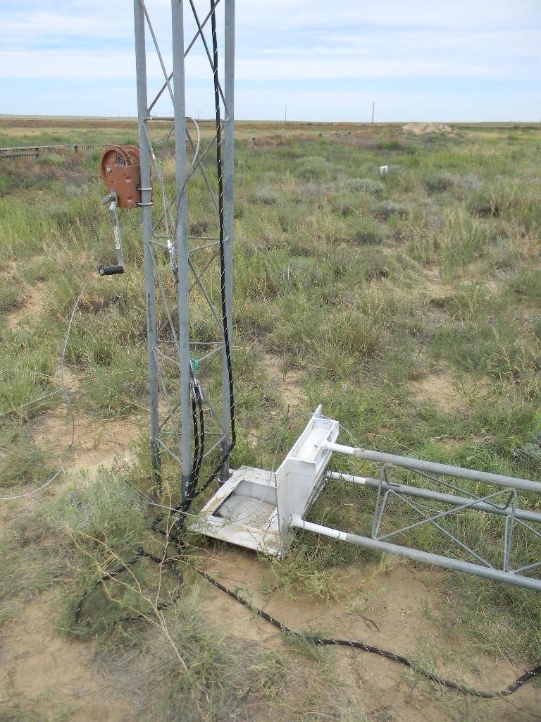
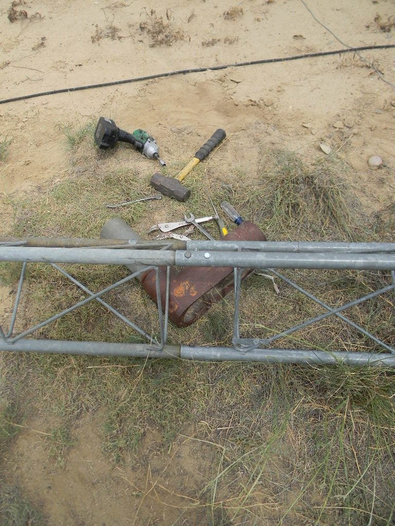
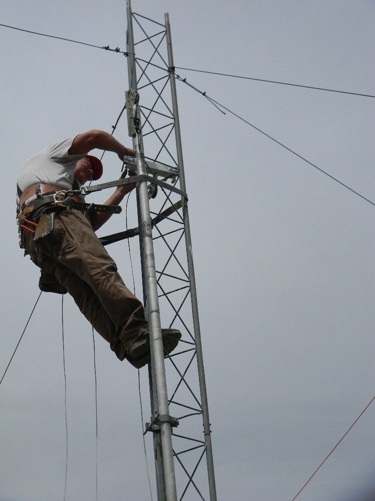
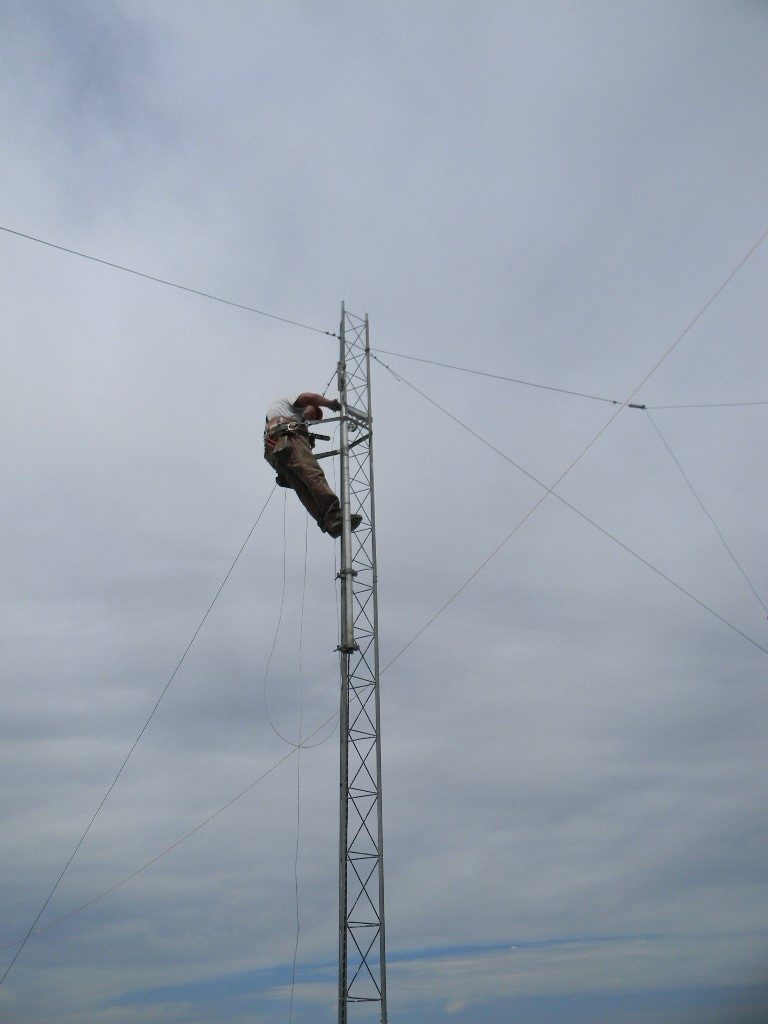
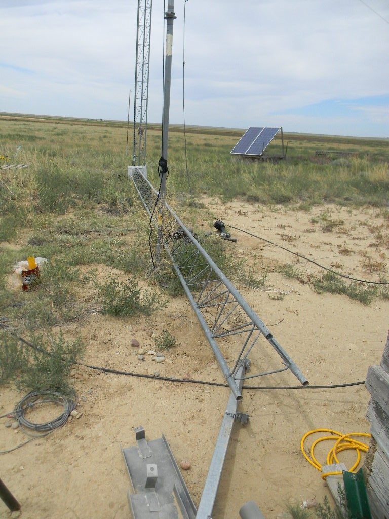
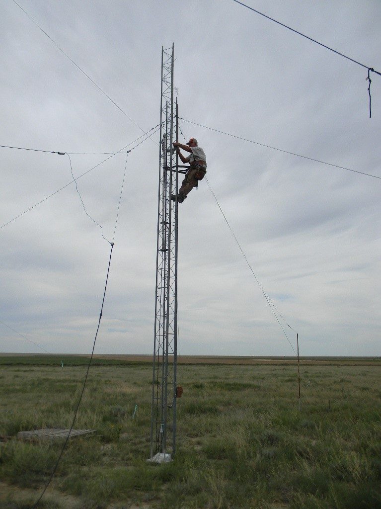
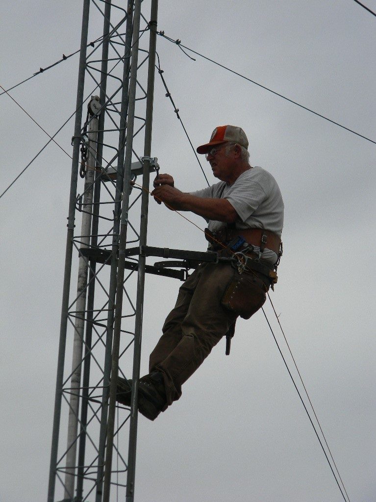
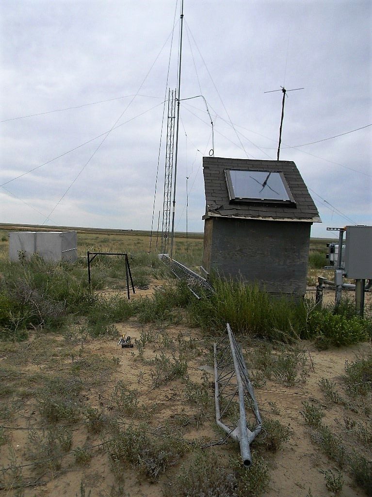
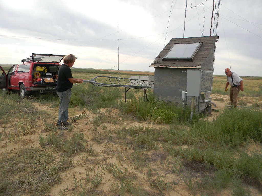
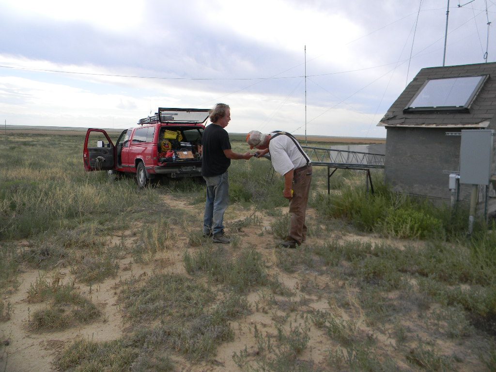
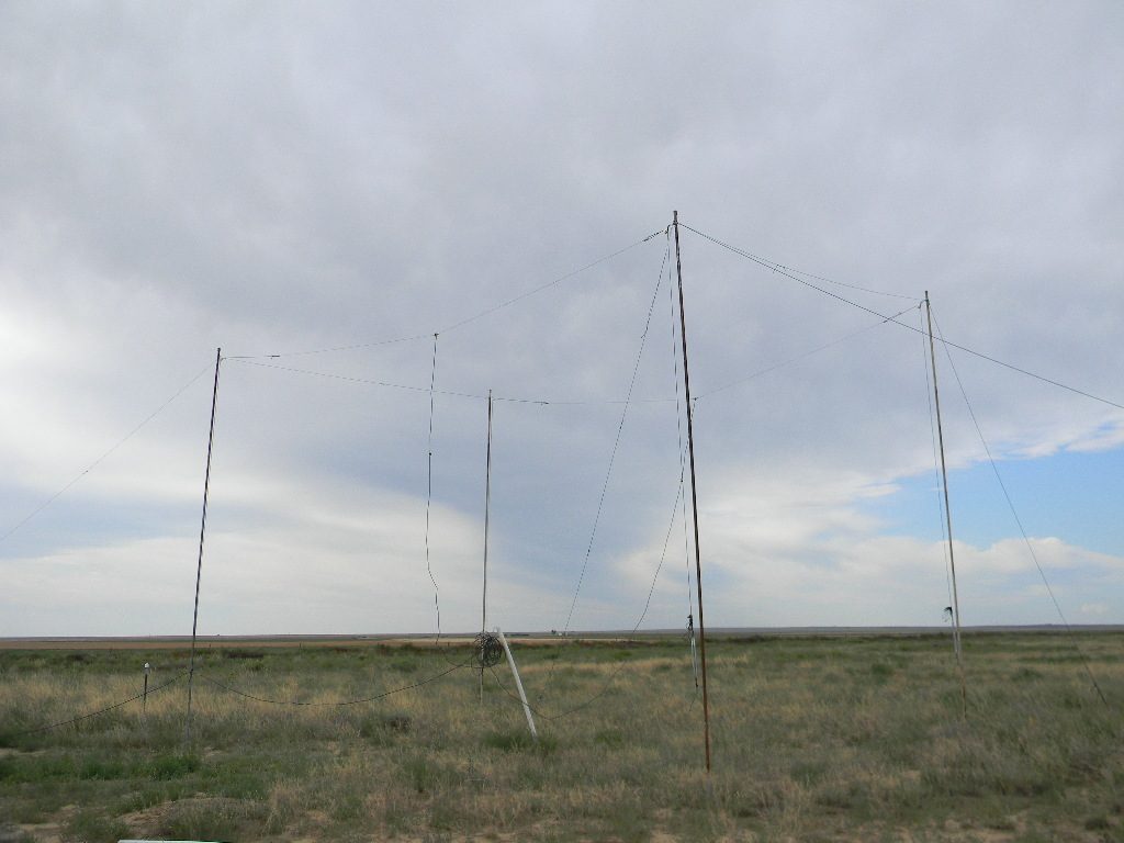
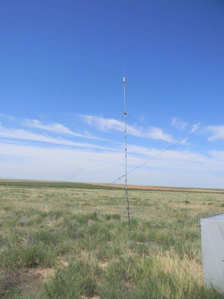
We assembled the tower components out to a length of 50 feet, including the top that will hold the rotor. The tower is now designed and built to rotate from a pivot point next to the existing tower that had been started earlier.  Ed climbed that original tower to install the pulley; the pulley leverages and pulls up the 50-foot tower by rotation at the pivot.  We tested lifting the 50 foot tower with the hand crank winch that I think came from Steve.  The design works.  We eventually will need to take down the mast that supports the 80 and 160 meter dipole antennas, to complete the tower build-out.  We plan to re-attaching those antennas to the tower itself, when we are ready to complete the tower.  Ed has already fabricated two standoffs that will attach to the sides of the tower, and centrally support the dipole antennas.

Ed from time to time went to help Steve. And Steve once in a while came to help with the tower assembly.

The base of the new antenna tower pivots next to the already existing support tower. The rotating winch on the support tower will pull the antenna tower and lift it up or down.
On each of the three connecting tubes, on each of the tower elements, a set of two screws each were bolted to fasten the connections.
Ed Corn attached a pulley (fabricated before) to the support tower.
Three of the 10-foot antenna tower sections connected, and connected with the base pivot. The cable from the winch has been threaded through the pulley on the support tower above, and connected to about the 20-foot point on the antenna tower. The pipe mast visible in the photo is the center support for the existing 80 and 160 meter dipole antennas. The new antenna tower, besides supporting the directional antennas at top, will replace that mast and support those dipoles.
We tested rotating up the antenna tower with three 10-foot sections assembled. After Ed verified that the placement of the pulley was good, he securely fastened it.
The winch with cable installed, used to lift and lower the antenna tower for service. The handle crank is geared. The lock pin enables free movement, movement in one direction, and locking.
The top section of the tower, ready to be attached.
Steve helped Ed and I complete the final assembly of the tower.

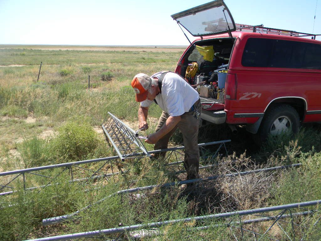
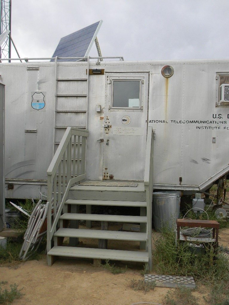
We had a lunch break together in the bunker. I brought a small coffee maker and brewed coffee for Ed and me.

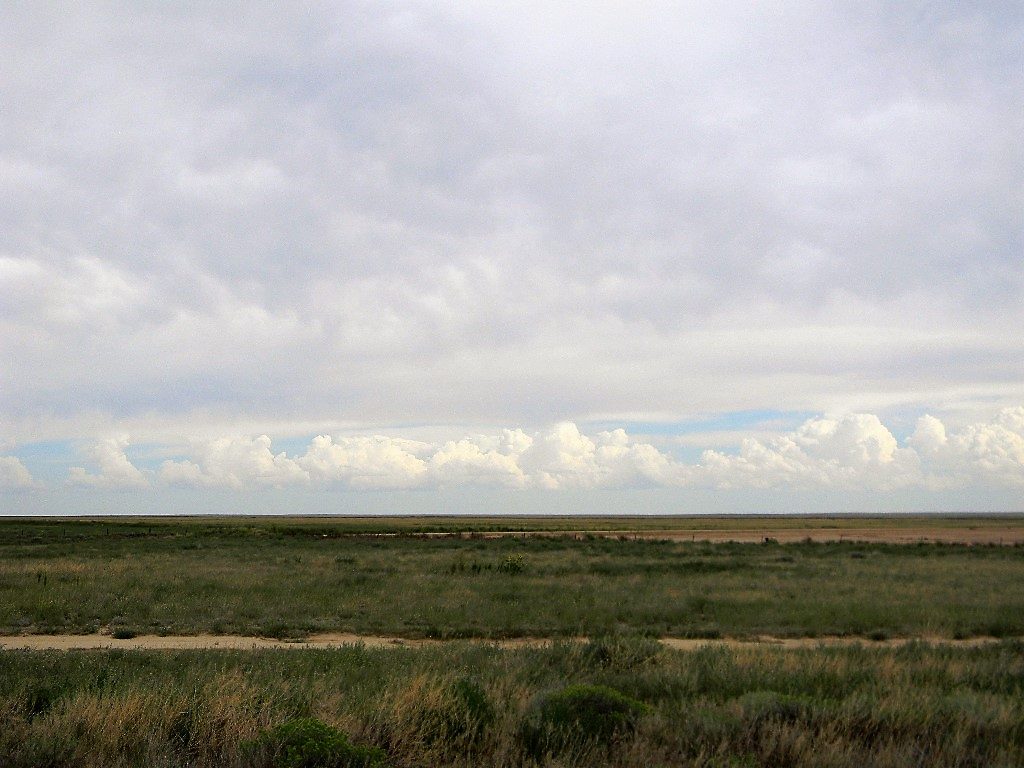
The weather was good, considering the heat we’ve been having lately.  High cirrostratus and mid level clouds from storms in the distance covered us for the afternoon, and kept the heat and sunshine comfortable.  We saw rain showers in the far distance, but those never came close enough to bother us. The bunker thermometer read 75 F, and outdoors was probably just a little warmer.

The Radio Jove phased dipole antenna array.
Bob Haggard’s steps provide much easier access to the Communications Trailer.
Sunflowers were blooming everywhere.
The bunker antennas in their configuration right now.

During a break I got on the air at the bunker station, and made 12 contacts for QSO parties that were running: 1 to Hawaii, 5 to Ohio, and 6 to Kansas, on CW and SSB, on 20 and 40 meters. I submitted our logs to those QSO parties later.

The 5 band vertical ham radio antenna, still in good working condition after the repair from the May storm. Photo taken in the late morning soon after we arrived. We used this to make our 12 ham radio contacts on the 20 and 40 meter bands.

For the team, Gary Agranat.

Radio Telescope Site Report, System 1 Team, August 17, 2019, by Glenn Davis

Here is a quick site trip report on the work the System 1 team (Phil Gage, Lewis Putnam, Dave Molter and Glenn Davis) completed at the Haswell Site yesterday (8/17/2019):

  1. We installed Version 4.0 of the System 1 software. This version includes a major new capability that supports manual tracking of astronomical objects. I would like to demonstrate this capability at the next Science or Engineering meeting.
  2. Version 4 included a software update to fix the Elevation Axis Bounce Issue (Erroneous Elevation Axis Status) that was identified earlier this summer and has been investigated for several years. The problem was related to the Elevation Axis Integrity Instruments 232M200 I/O module. Due to a board related hardware problem, the I/O board was always reporting bit 2 of the encoder position data as “stuck” on (1) which would create erroneous Elevation encoder data. The fix required both a hardware and software modification. The hardware modification included moving the bit 2 pin to an unused position on the connector to the I/O module (see #3) then provide a software fix that would read data from this new bit position and re-incorporate the bit data back into the Elevation encoder position data – bypassing the bad bit. This hardware/software solution has fixed the problem. The Elevation Axis is now providing the correct encoder positions through it’s range of motion and the “bouncing” has been eliminated.
  3. Dave Molter moved and soldered the “bad” Elevation Axis hardware pin to support the software modification that fixes the Elevation Axis Bounce issue.
  4. Collected Voltage to Rate information for both axis – data below:
Voltage (V) Azimuth Rates (Degs/Sec) Notes
0.00 0.00 Minimum Potentiometer Setting
0.20 0.04
0.39 0.08
0.50 0.11 Normal Potentiometer Setting
0.75 0.17
1.50 0.33
Voltage (V) Elevation Rates (Degs/Sec) Notes
0.05 0.06 Minimum Potentiometer Setting
0.17 0.07
0.35 0.08
0.75 0.11
1.52 0.15 Normal Potentiometer Setting
3.72 0.30
4.24 0.34
5.00 0.42

Please note: We were unable to produce zero rates on the elevation axis – even with the potentiometer turn all the way down.

Additionally, though we believe we returned the potentiometers back to their normal positions, whoever returns to the site for the next data collection, please ensure the potentiometers are at their normal positions before use.

Glenn Davis

Radio Search for Extraterrestrial Intelligence SETI is fun ! – August 2019 SARA Presentation by Skip Crilly

This is Skip Crilly‘s updated paper/presentation, Radio Search for Extraterrestrial Intelligence SETI is fun ! Geographically-spaced Synchronized Signal Detection System, updated July 2019. Skip presented it at the Society of Amateur Radio Astronomers conference at Greenbank, WV on August 4, 2019. The link will open as a pdf file.

Radio Search for Extraterrestrial Intelligence SETI is fun ! Geographically-spaced Synchronized Signal Detection System

These two wave files are part of the presentation:  Figure 9 Simultaneous Tones Slow wave file and Figure 9 Simultaneous SETI Tones wave file.