A Major Milestone for the Deep Space Exploration Society – Please Donate
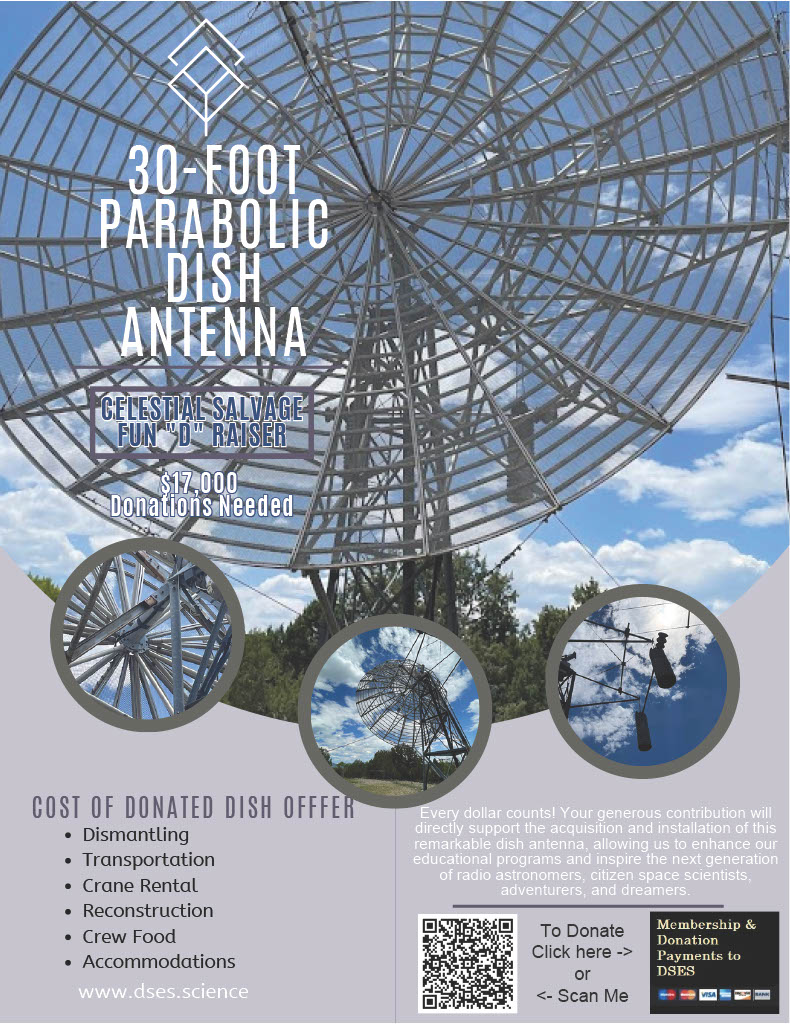
We need to raise $50,ooo to complete the installation of a recently acquired 30-foot dish – here is the story and how you can contribute.
In June 2024, the Deep Space Exploration Society (DSES) completed one of the largest and most ambitious field operations in its history: the rescue of a 30-foot parabolic radio dish antenna that was just days away from being cut up for scrap.
This dish—graciously donated by Patti Clark, widow of the late Robert B. Clark, K0YW—is now safely in Colorado and will soon be reassembled at the DSES Radio Astronomy Site in Haswell.
Why This Dish Matters
Large-aperture antennas of this size are rare, expensive to build, and invaluable for radio astronomy, deep-space signal work, and STEM education. Securing this dish expands our long-term capability to:
- Train students in hands-on radio science and engineering
- Support NASA and citizen-science space missions
- Conduct deep-space observations and research
- Preserve and demonstrate legacy amateur-radio technology
This rescue ensures that Robert Clark’s passion for radio science will continue to inspire future generations.
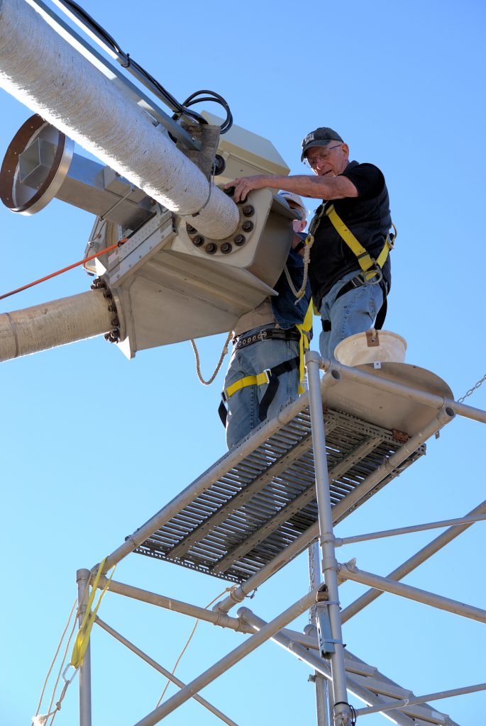
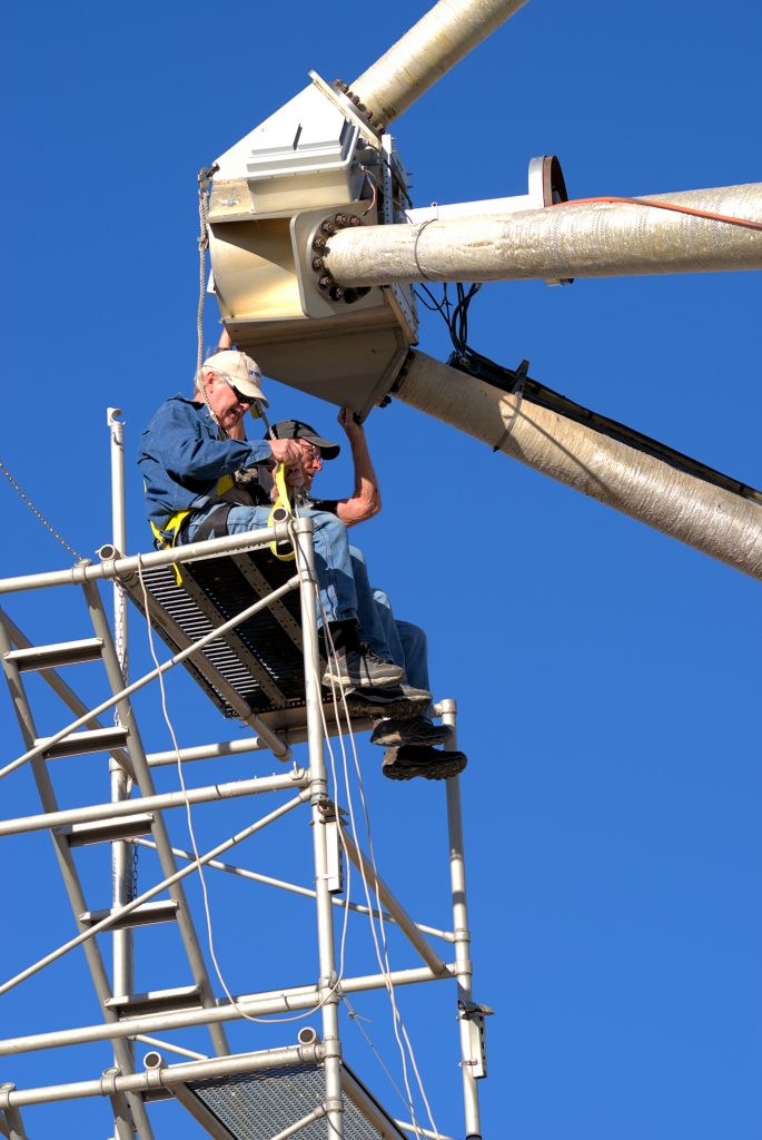
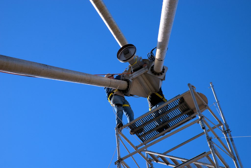
The Rescue Operation (June 23–26, 2024)
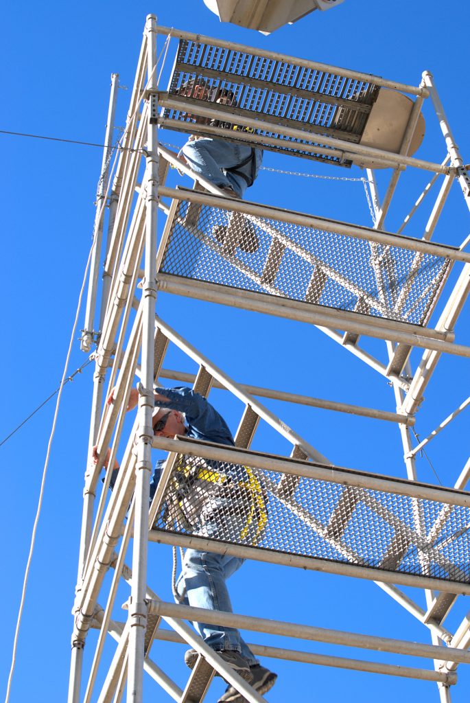
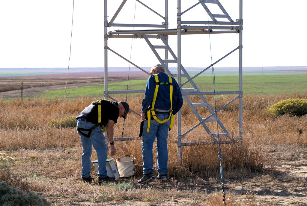
A dedicated nine-person DSES crew traveled to Ignacio, Colorado, to dismantle and recover the antenna under challenging and often hazardous conditions.
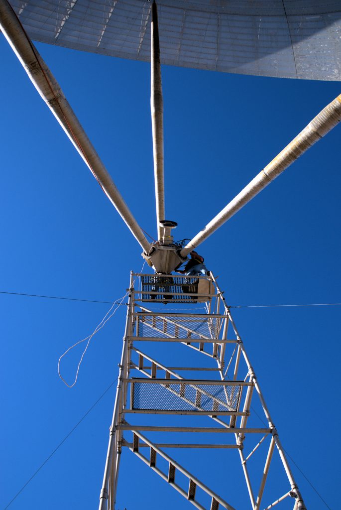
- The dish was found in a sideways orientation, making disassembly far more difficult.
- Temperatures routinely exceeded 90°F with no shade.
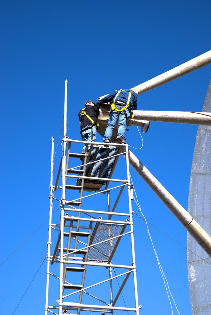
- Crane and man-lift operations required careful coordination and safety planning.
- Every component—from tower sections to counterweights—was photographed, labeled, and preserved.
Despite initial doubts from even the crane operator, the team developed a safe method to remove the feed, counterweights, support structure, tower, and dish.
Hundreds of bolts, brackets, and assembly parts were marked, cataloged, and stored for accurate reassembly.
Rescue Team
Myron Babcock KL7YY (project lead),
Chas Barrett WD0C, Richard Hambly K0GD, Roger Oakey W3MIX,
Paul Sobon NO0T, RC Teal AI0RC, Ray Uberecken AA0L,
and Elaine Hambly K0ARR (photographer)
“One of the Most Challenging Projects We’ve Attempted”
DSES member Elaine Hambly, K0ARR, captured the experience in her field report: Save the Dish Report
“When we arrived on June 23rd, we faced what looked like an impossible task… The dish was sideways instead of upright, and even the crane operator had doubts.
Our team planned every step, documented every part, and endured long hot days to save this antenna.
Transport to Haswell
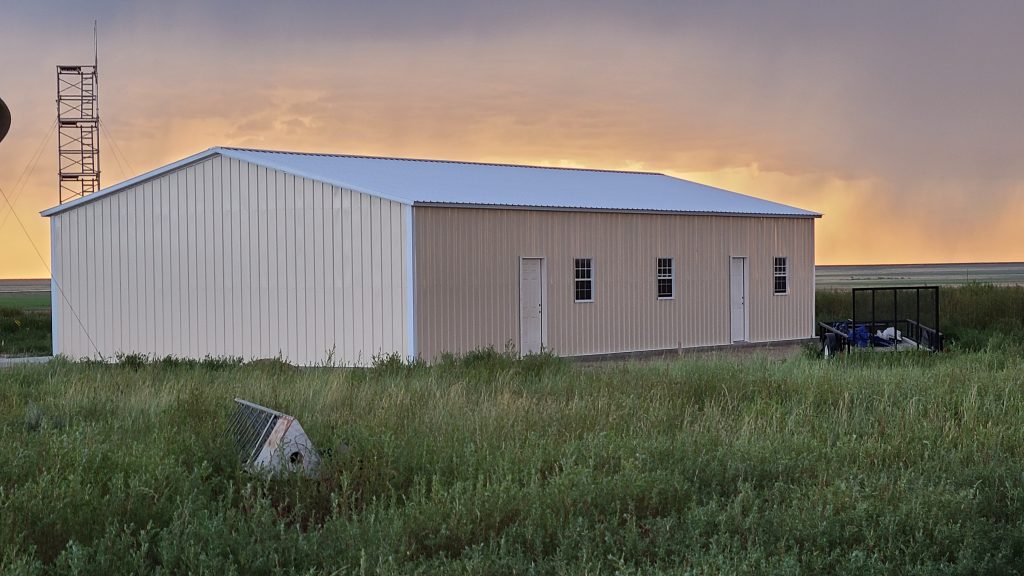
The following week, three fully loaded trailers carried the rescued components to the DSES site in Haswell, Colorado.
A larger volunteer crew—including Bill Miller KC0FHN and others—unloaded the parts and moved them into temporary storage.
The dish sections, tower components, pedestal, struts, counterweights, Rohn 45 sections, and hardware are now secured on-site and ready for reconstruction.
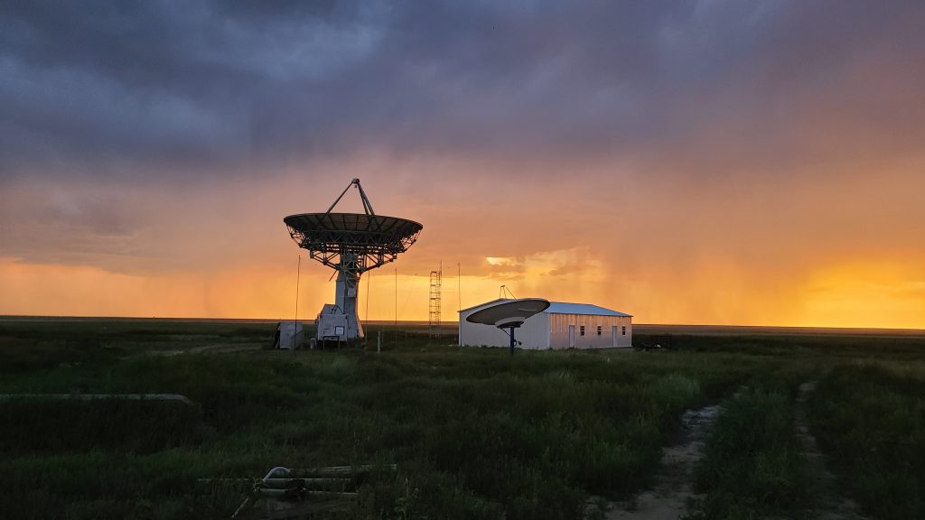
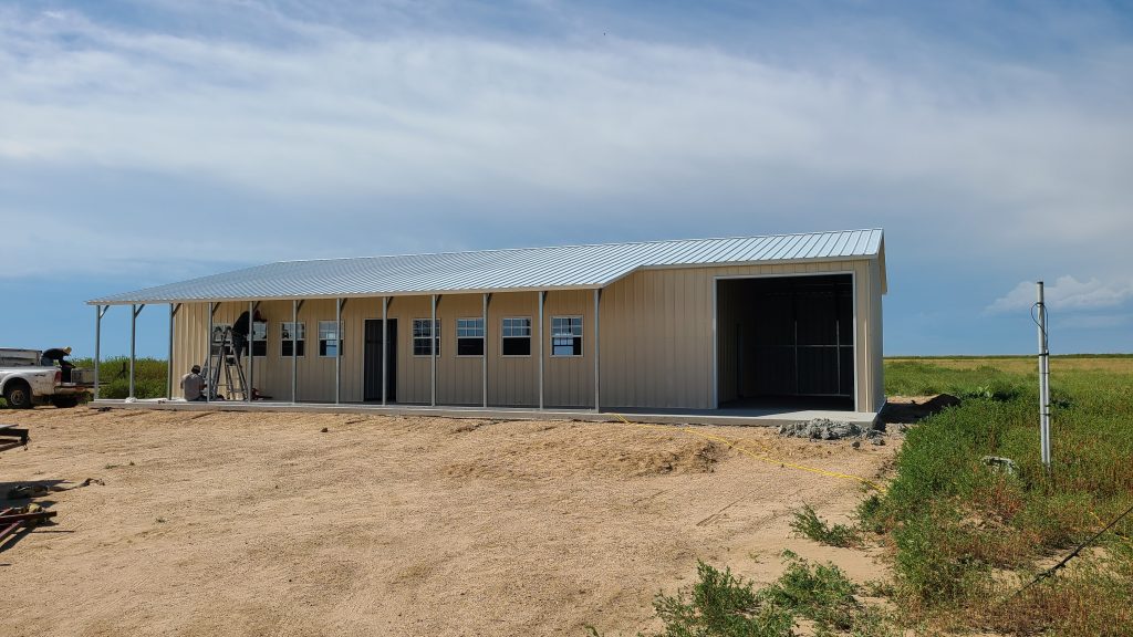
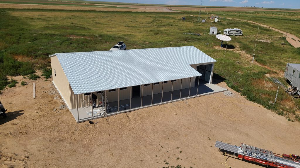
Next Phase: Rebuilding the Dish at Haswell
The 30-foot dish will be installed on a new concrete foundation engineered for long-term scientific use.
Once reassembled, this instrument will:
- Expand our educational programs
- Support deep-space and hydrogen-line observations
- Provide backup and experimental capability alongside the 60-foot dish
- Serve as a laboratory for students, educators, and citizen scientists
This will be one of the most significant upgrades to the Haswell facility in over a decade.
How You Can Support the Rebuild
DSES is now seeking financial support to fund:
- Concrete foundation construction
- Crane and heavy-equipment operations
- Mechanical and structural refurbishment
- Electrical, control, and RF system integration
Your tax-deductible donations will directly accelerate the reconstruction.
Donate Online:
Contact:
Paul Sobon, NO0T
President, Deep Space Exploration Society
303-601-5773
pauls@dses.science
A New Chapter for DSES
The successful rescue of the 30-foot dish marks the beginning of an exciting new chapter for the Deep Space Exploration Society.
With your support, this instrument will soon help advance STEM learning, radio astronomy research, and community science for years to come.