Doug Leber provided the following report on the recent Las Animas High School Visit to the DSES site:
The Deep Space Exploration Society (DSES) hosted its first high school field trip on Wednesday, January 22, 2025, when seventeen Las Animas High School students and three staff members toured the Plishner Radio Astronomy and Space Sciences Center outside Haswell, CO. About half the students will participate in this year’s Colorado Science Olympiad competition. Jennifer Pointon, Science Olympiad coach, and Las Animas High School counselor, said she wanted students to see the Plishner facilities and learn how DSES can provide opportunities for research and mentorship in astronomy, radio, electronics, and engineering. Joshua Japhet (Las Animas HS Dean of Students and Science teacher) and Cody Hines (Las Animas HS Instructional Coach) also helped make this visit successful.
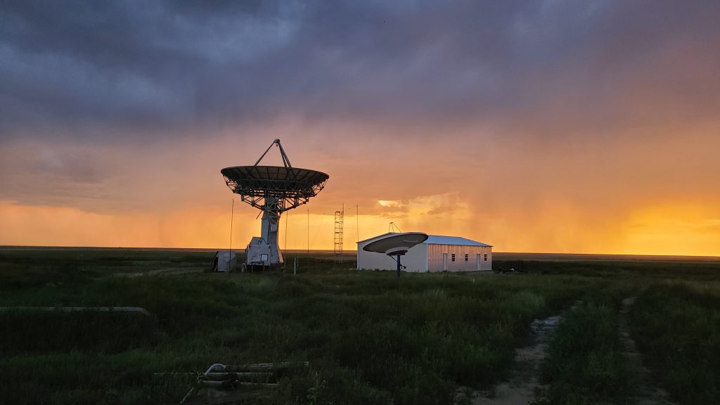
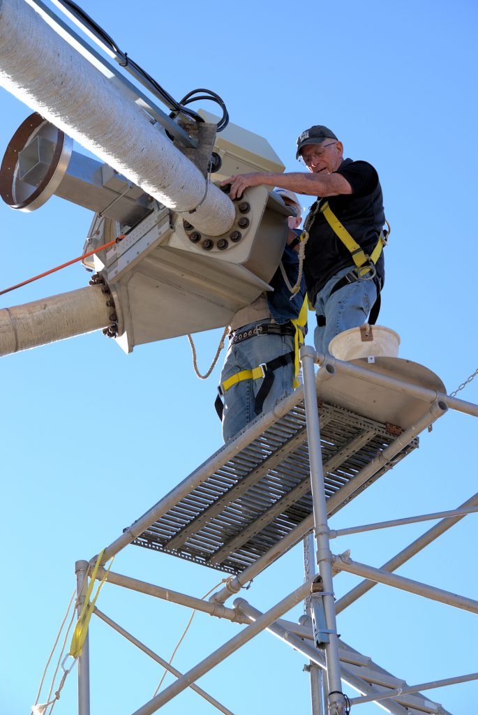
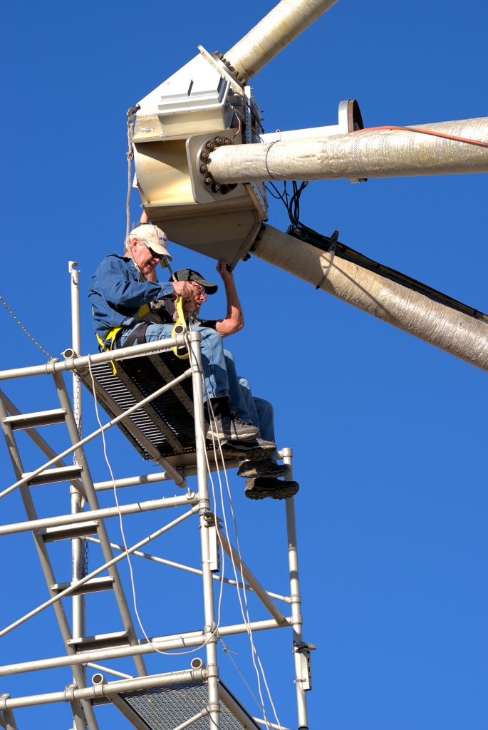
Bill Miller, DSES Vice President, gave an overview of the organization’s history and the years of effort required to revive the 60-foot-diameter radio telescope at the Haswell site. He introduced radio astronomy and some of the studies DSES members have conducted since restoring the telescope, including detecting pulsars and masers, observing solar and planetary radio emissions, and mapping the hydrogen line to show which galaxies are moving toward or away from Earth.
DSES Board member Ray Uberecken and DSES member Roger Oakey showed students how we control the dish to track and focus on deep space objects as Earth revolves. Mr. Japhet said students enjoyed watching how the huge dish moved. Mr. Uberecken also showed different ways radio frequency signals are represented, using an oscilloscope to show a signal’s waveform in real-time (the frequency and shape of an electrical signal) and the same signal in a waterfall display, which shows its intensity and relationship to other signals nearby on the radio spectrum.
Students then braved the intense winds and cold to venture to the bunker location of the DSES amateur radio station, where Board member Paul Sobon demonstrated how long-distance contacts are made using high-frequency (HF) transceivers. Under his supervision, several students learned to call ‘CQ,’ the amateur radio shorthand for “I’m here and ready to take your call!” Unfortunately, because band conditions were poor, no student got a response. Later, Paul Sobon reached a radio amateur in the Canary Islands, and students observed two-way HF radio communication between stations over 5,000 miles apart.
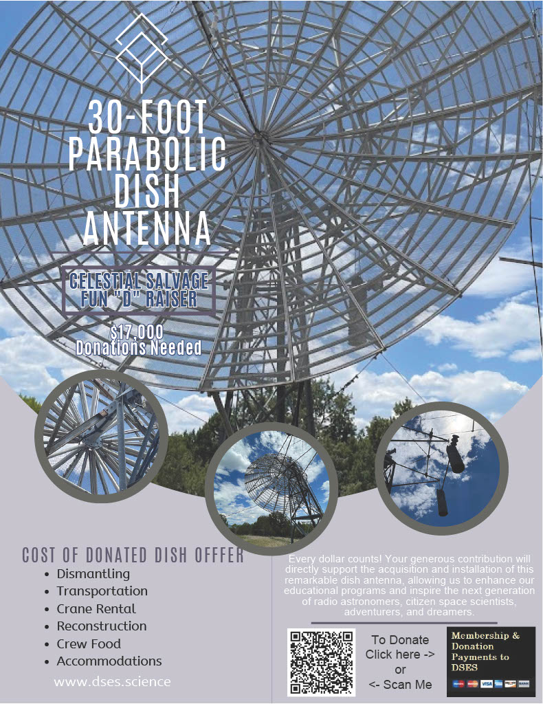
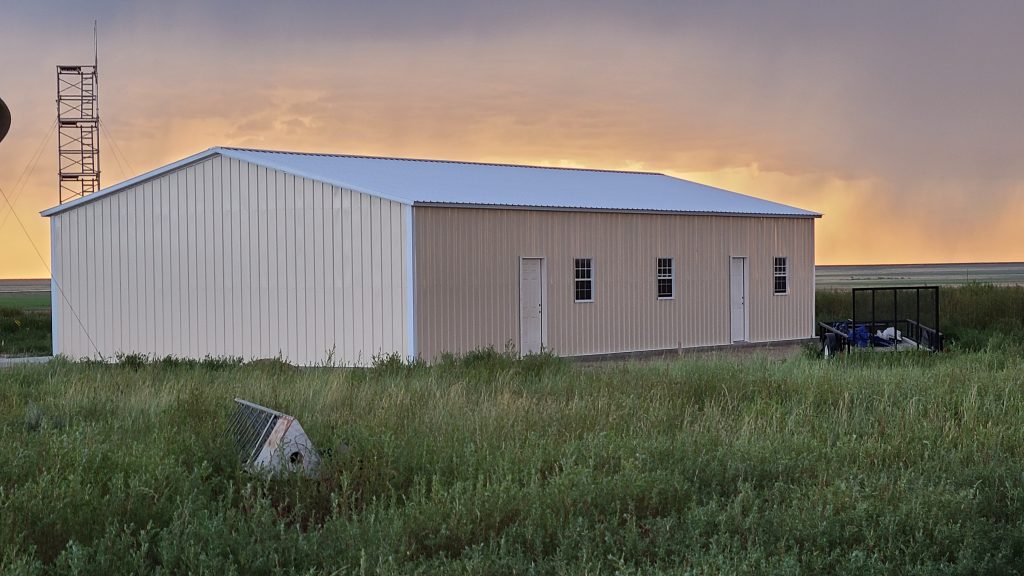
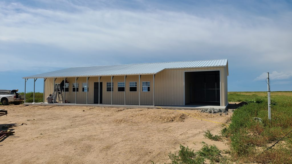
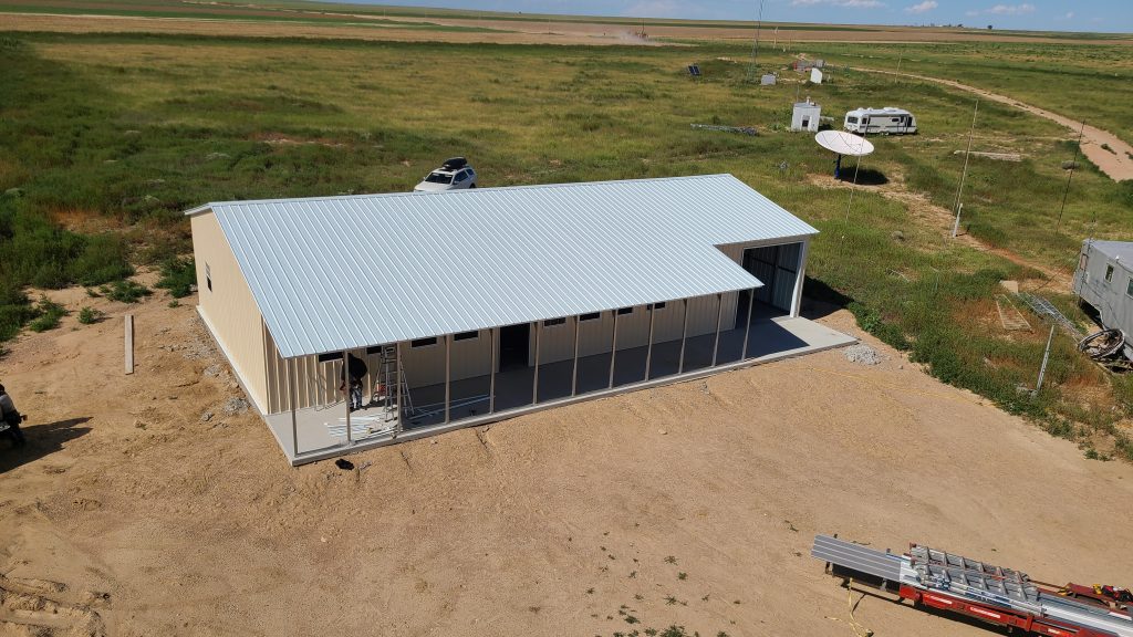
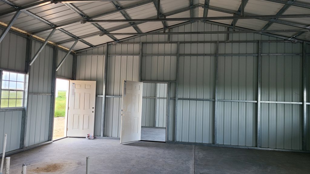
Since 2009, society members have devoted hundreds of hours to rebuilding the Plishner site. In 2023, a grant from Amateur Radio Digital Communications (ARDC) provided funds to complete a new building suitable for hosting groups.
DSES President Myron Babcock noted that this field trip visit to the Plishner Radio Astronomy and Space Sciences Center reflected the dreams of Michael Lowe, former Board DSES Board President, who sought to create a center for radio astronomy and space science education in Southeast Colorado. Over the next year, DSES hopes to host more school trips to the Plishner Center and work with area middle- and high-school students to advance their studies in science and radio.
If you are a parent, teacher, or school representative interested in learning more about DSES and how the society can support your students, please contact Doug Leber, the DSES education outreach coordinator.