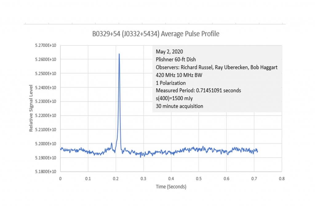
The pulsar, B0329+54 (J0332+5434)1, was observed on the third try just before the team was ready to pack up for the day on Saturday, May 2, 2020. A final modification of the software defined radio settings was tried (all the gains were set to a minimum) did the trick.
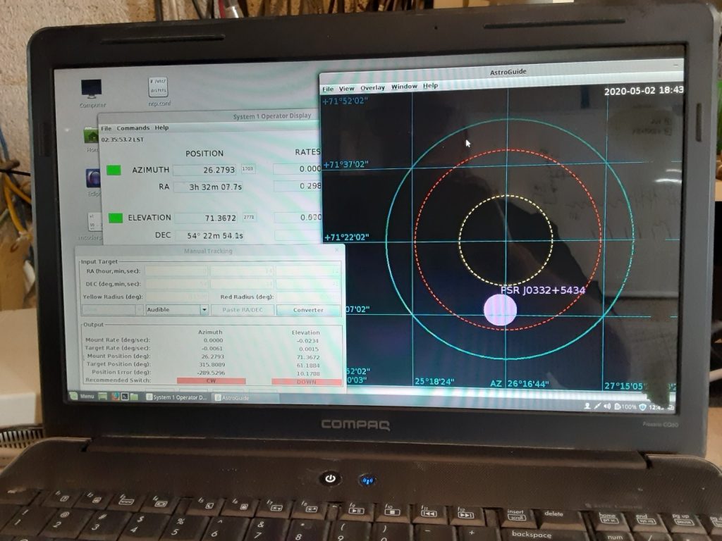
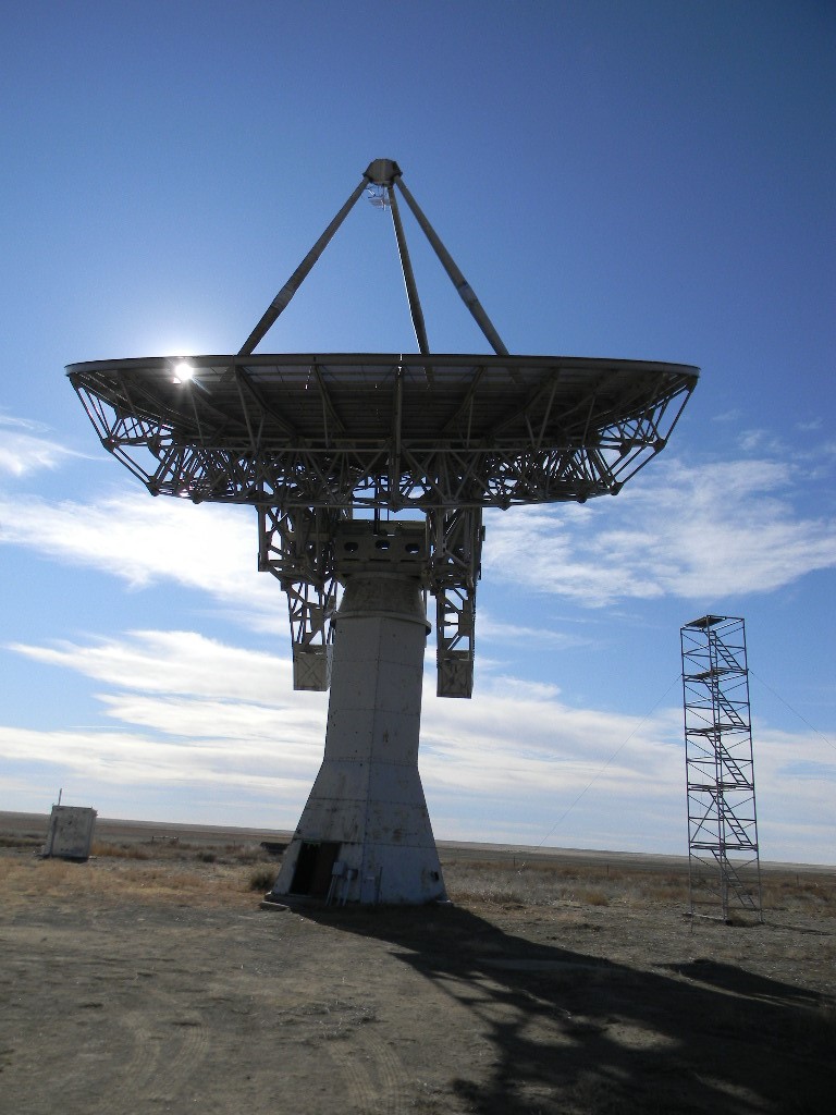
The 60-ft dish was setup to manually track the pulsar using the System 1 tracking program software developed by Glenn Davis and Phil Gage. This program allowed us to track the pulsar’s position by keeping it in the bullseye.
We observed at a frequency of 420 MHz, with a bandwidth of 10 MHz.
The pulsar system was initiated last year by Steve Plock. Our mentor throughout the effort has been Dr. Joe Martin (K5SO) in New Mexico. Joe validated that we made a successful pulsar capture.
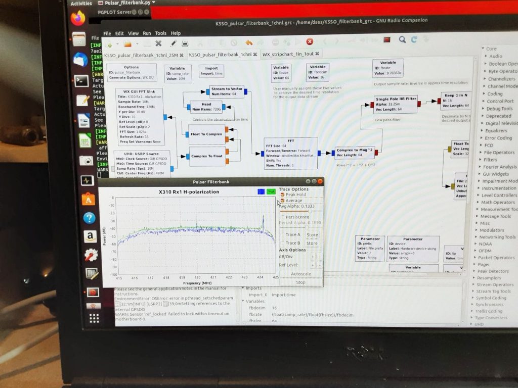
The GNU radio software was turned on to start the
acquisition.
It should be noted that
you cannot tell if you have the pulsar real-time because it is pulsing way
below the noise level. After about 30 minutes, we stopped the acquisition and
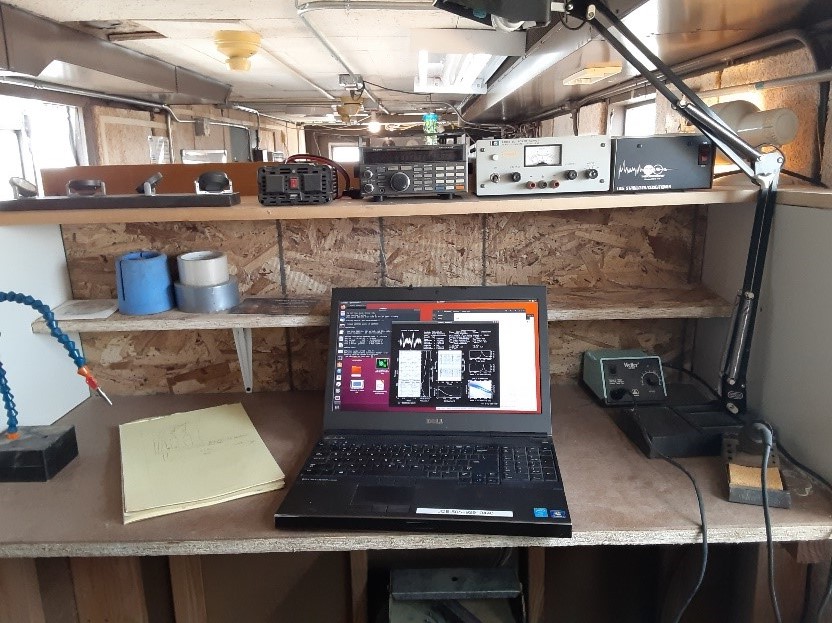
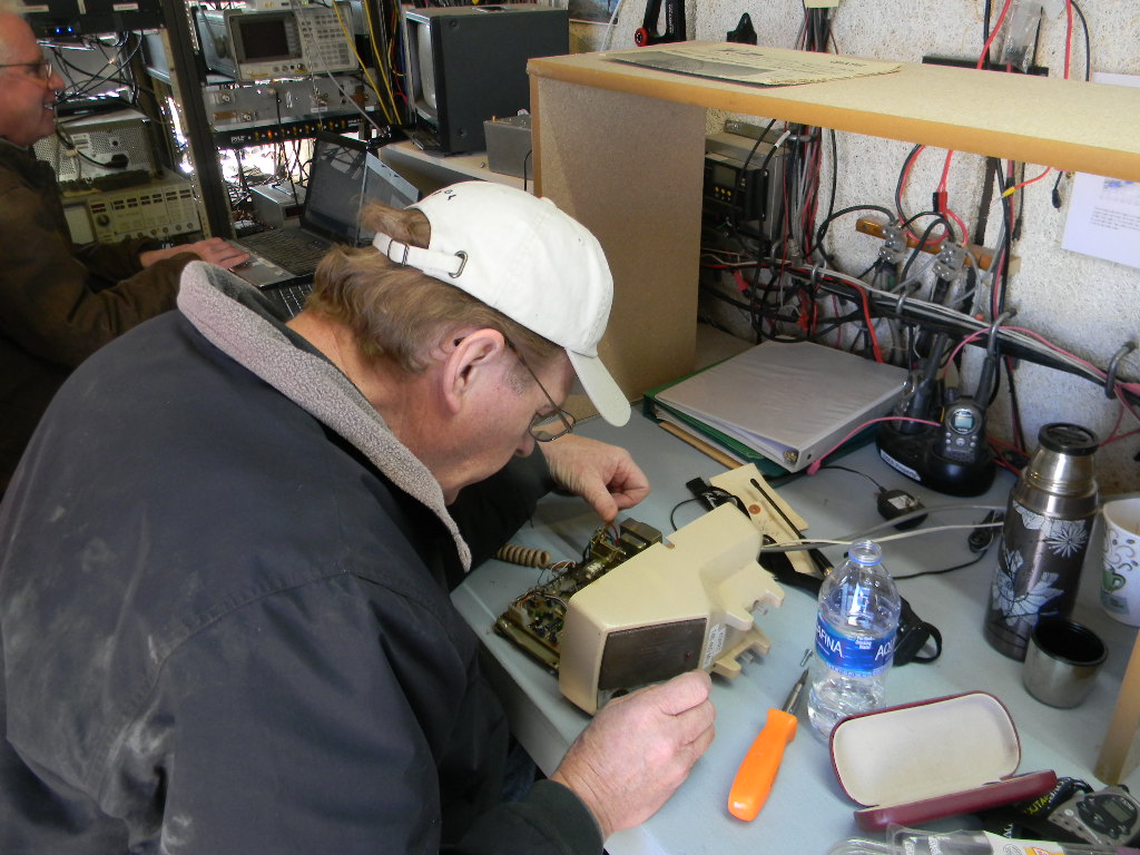
we moved the post-processing over to Bob’s new workbench.
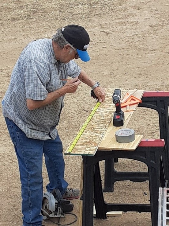
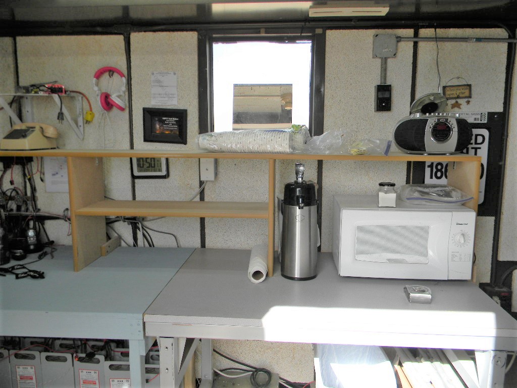
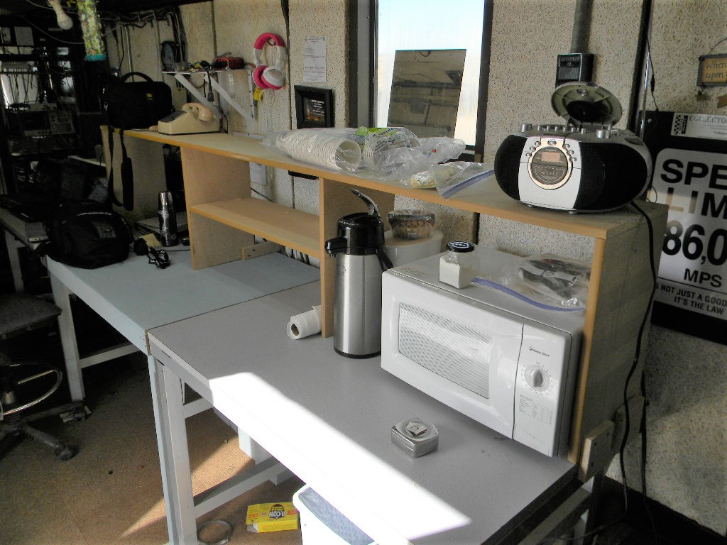
Bob Haggart constructing the new workbench.The new workbench in the science trailer, built by Bob Haggart.
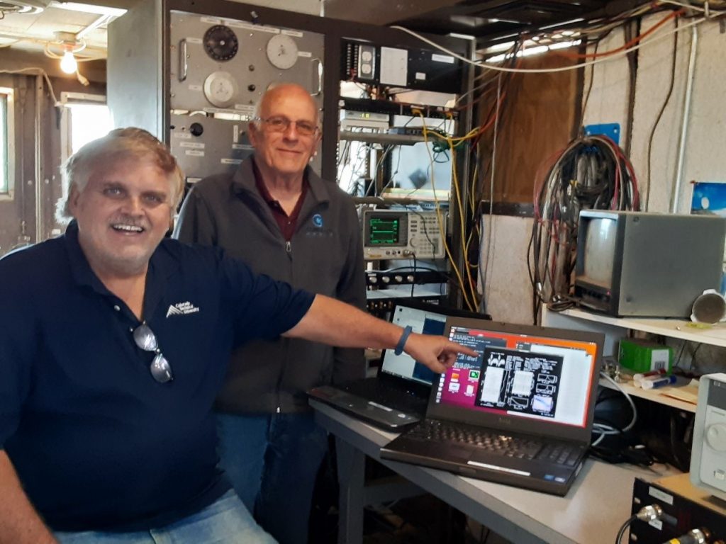
Rich and Ray celebrate
our first pulsar! (Bob’s taking the picture)
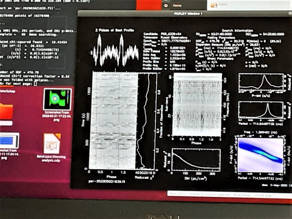
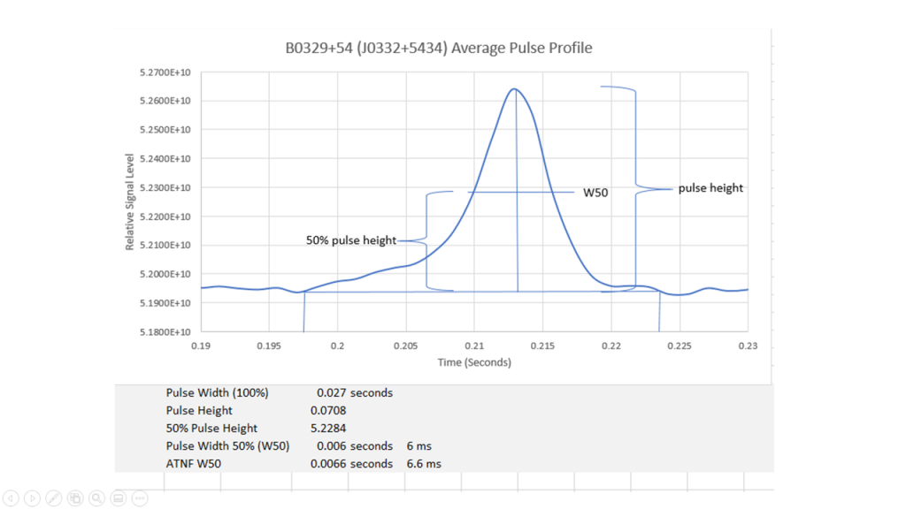
The first iteration of post -processing requires that the pulsar period be estimated with a program called TEMPO. The first iteration is shown below. It clearly shows a pulsar because of the prominent peaks and the lines tracing down the plots, however it is not quite set to the optimum period.
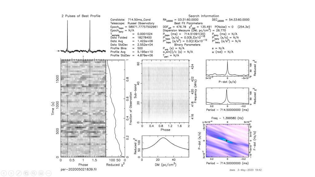
After some more iterations the final picture looked cleaner.
More analysis using the resultant data files allowed us to verify the pulsar as B0329+54 (J0332+5434).
Even the
pulse width at the 50% height (W50) was estimated. The preliminary analysis
below shows a measured W50 of 6 ms. The current value in the ATNF database is
6.6 ms. This is real close and confirms our observation.
More observation runs are planned and DSES can can consider itself one of the few amateur organizations to accomplish pulsar observations2.
Reference:
PSR B0329+54 is a pulsar approximately 3,460 light-years away in the constellation of Camelopardalis. It completes one rotation every 0.71452 seconds and is approximately 5 million years old.[Ref: wikipedia]
Participants: Rich Russel, Bob Haggart, Glenn Davis, Lewis Putnam, Bill Miller, and Gary Agranat.
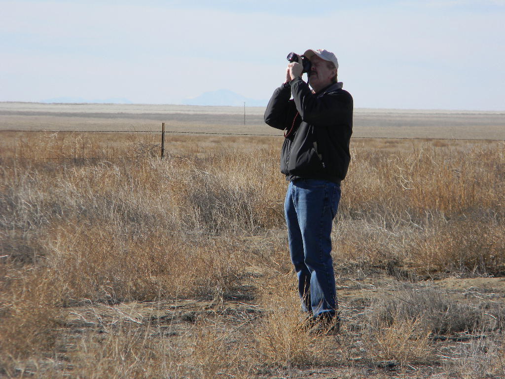
Photos by Bill Miller and Gary Agranat.
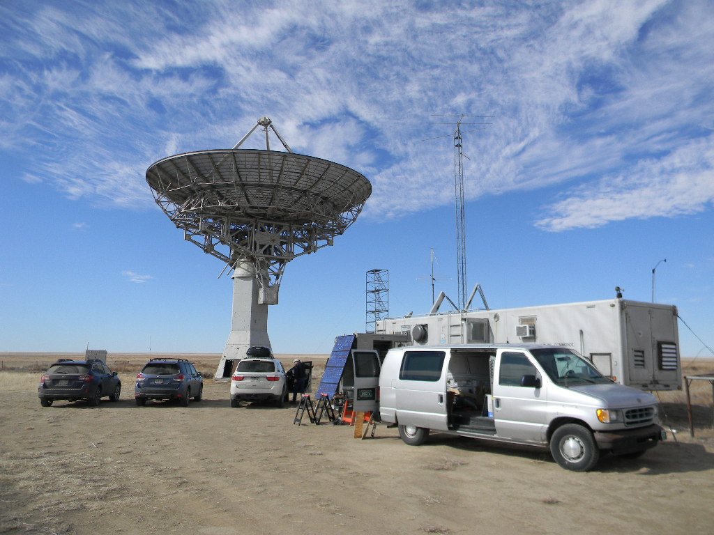
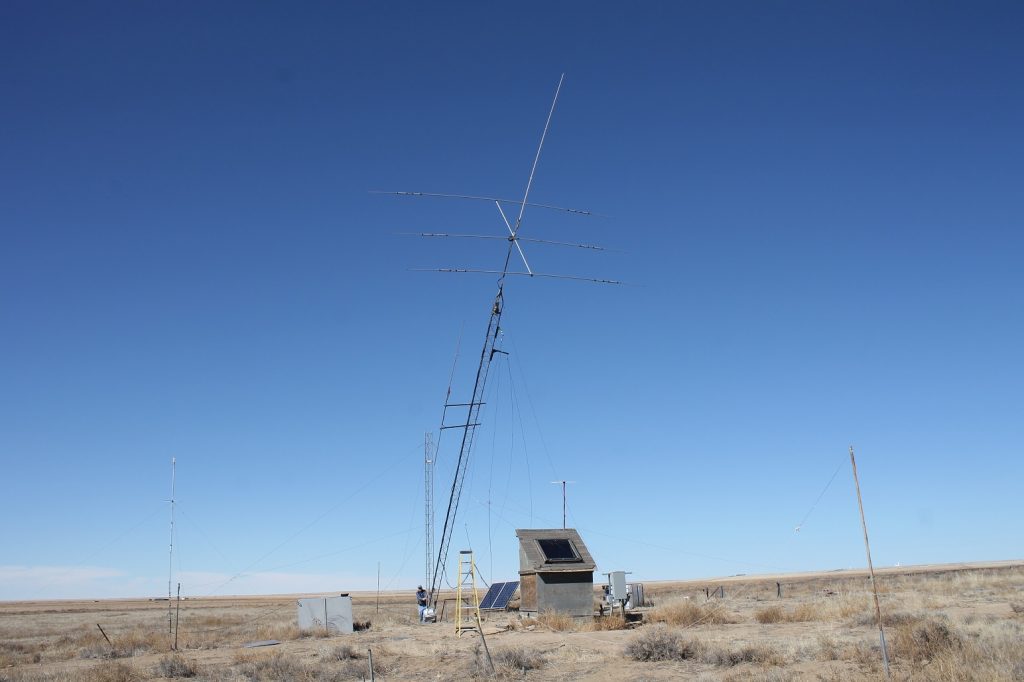
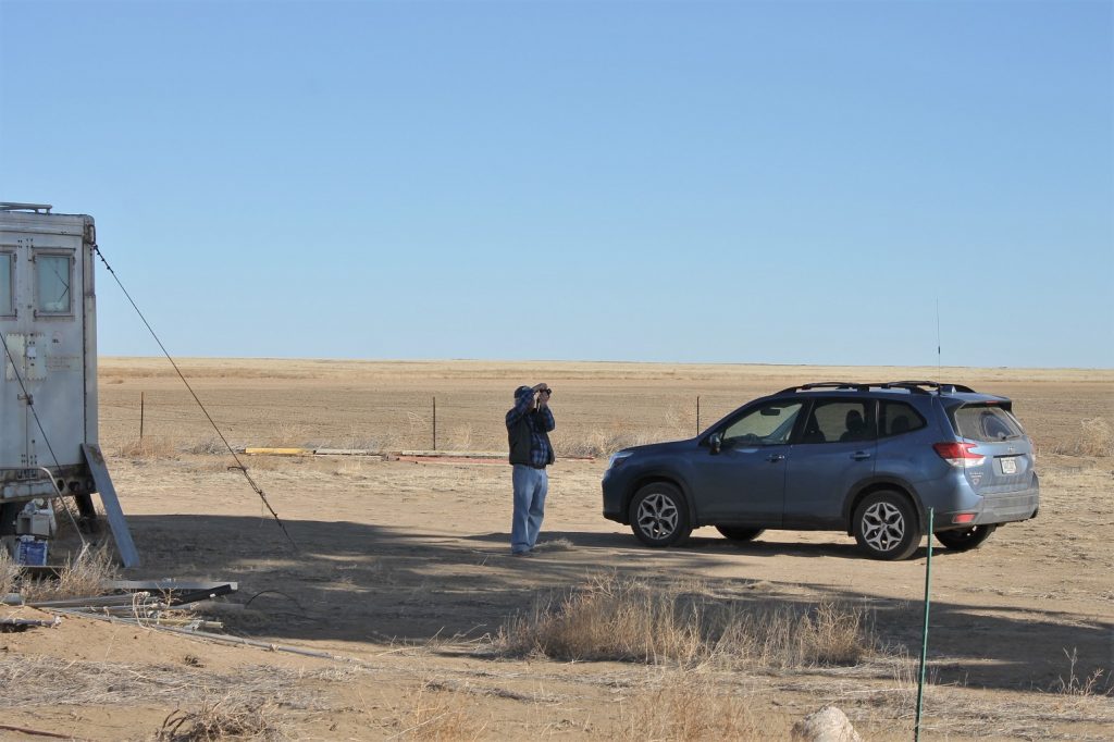
We worked at the Plishner antenna site in Haswell on Saturday February 15, 2020. We had three projects:
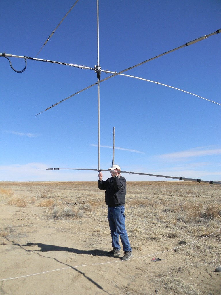
Attempt at observing a circumpolar pulsar, utilizing the System 1 manual tracking system. (Rich Russel, Glenn Davis, Lewis Putnam).
Complete building and installing shelf space in the Communications (Operations) Trailer (Bob Haggard).
Repair of the 3-element Yagi ham radio antenna, to realign the three elements (Gary Agranat, Bill Miller, Bob Haggard).
1. The major task of the day was an attempt at a science observing run of a circumpolar pulsar. This is one of the brighter puslars in the sky. And being circumpolar, it is always above the horizon, though it can still get relatively low to the horizon. The observing technique required continually pointing a the celestial coordinates and integrating the signal for at least a half hour. By integrating over time, the random noise tends to cancel more, leaving the actual radio source signal the time to accumulate and sum to a higher level than the noise floor.
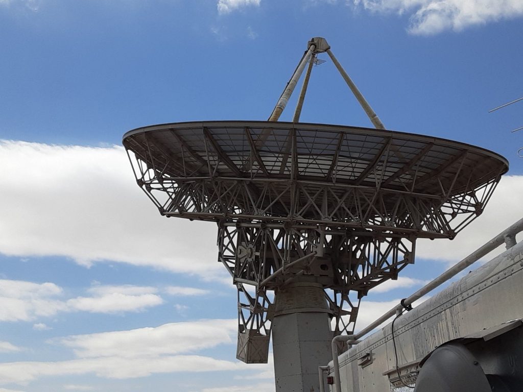
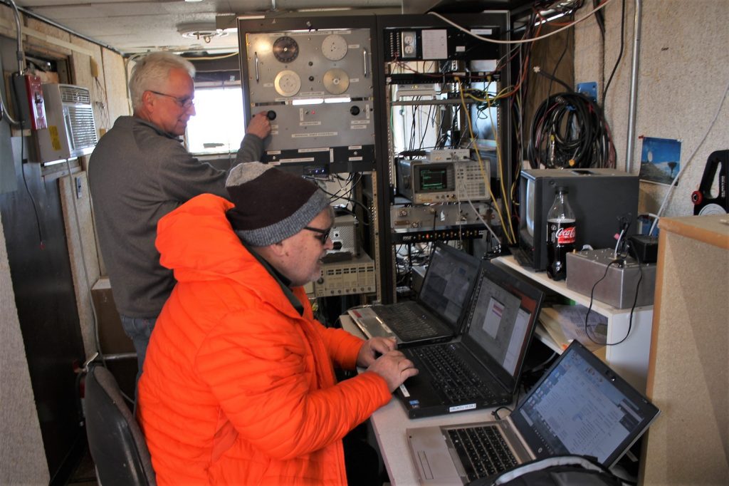
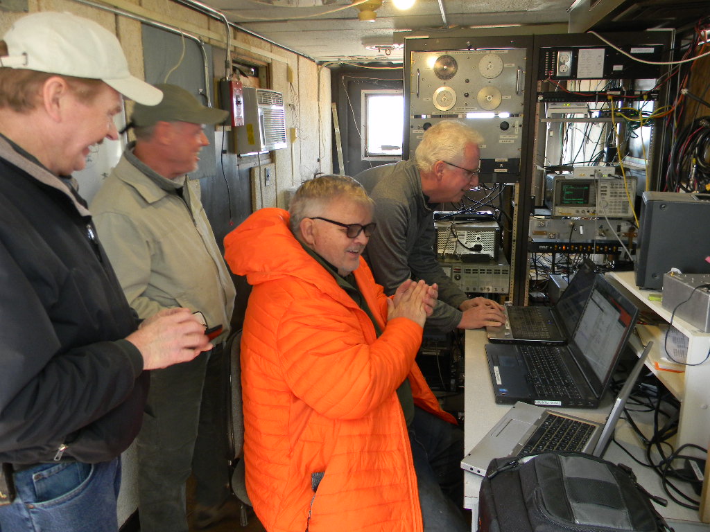
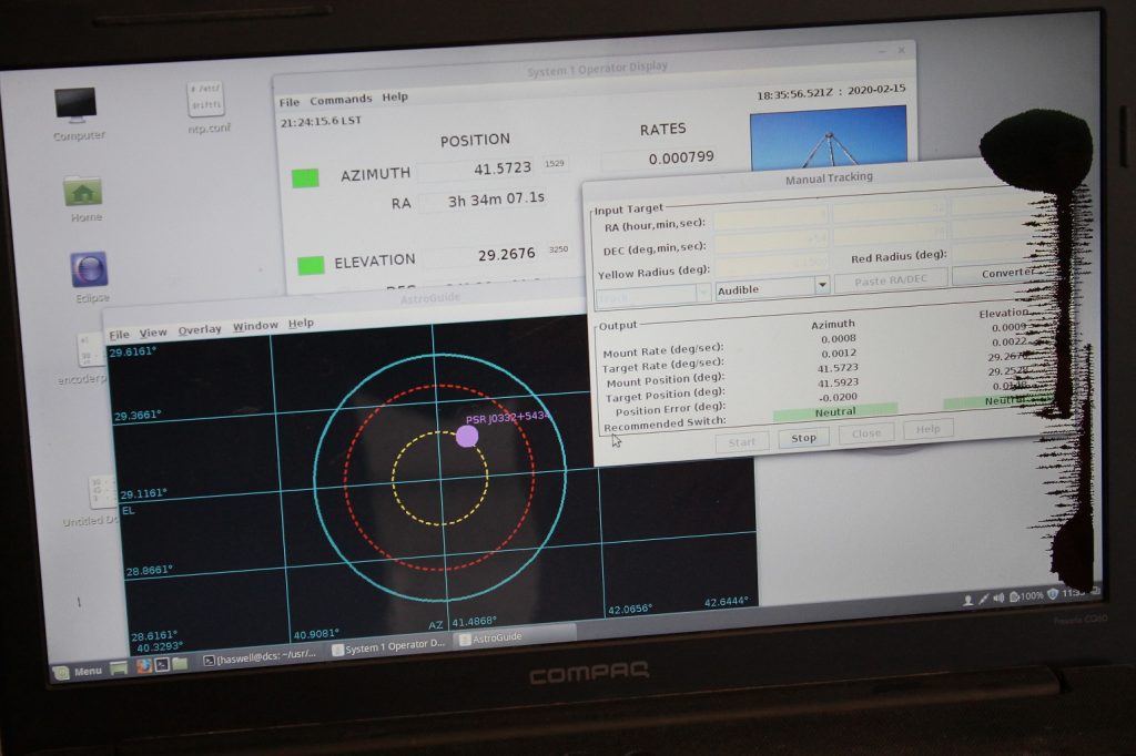
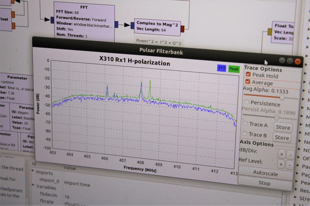
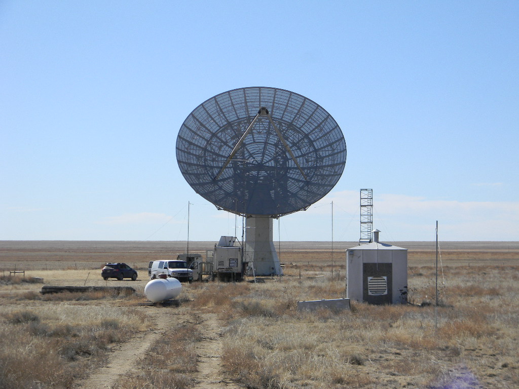
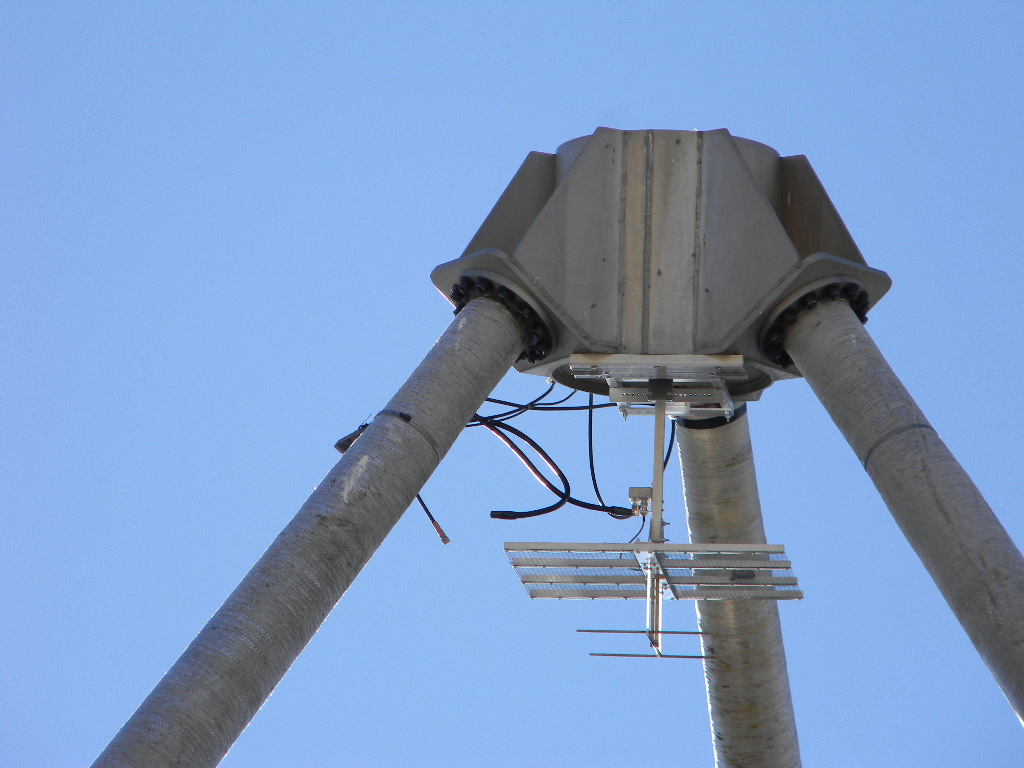
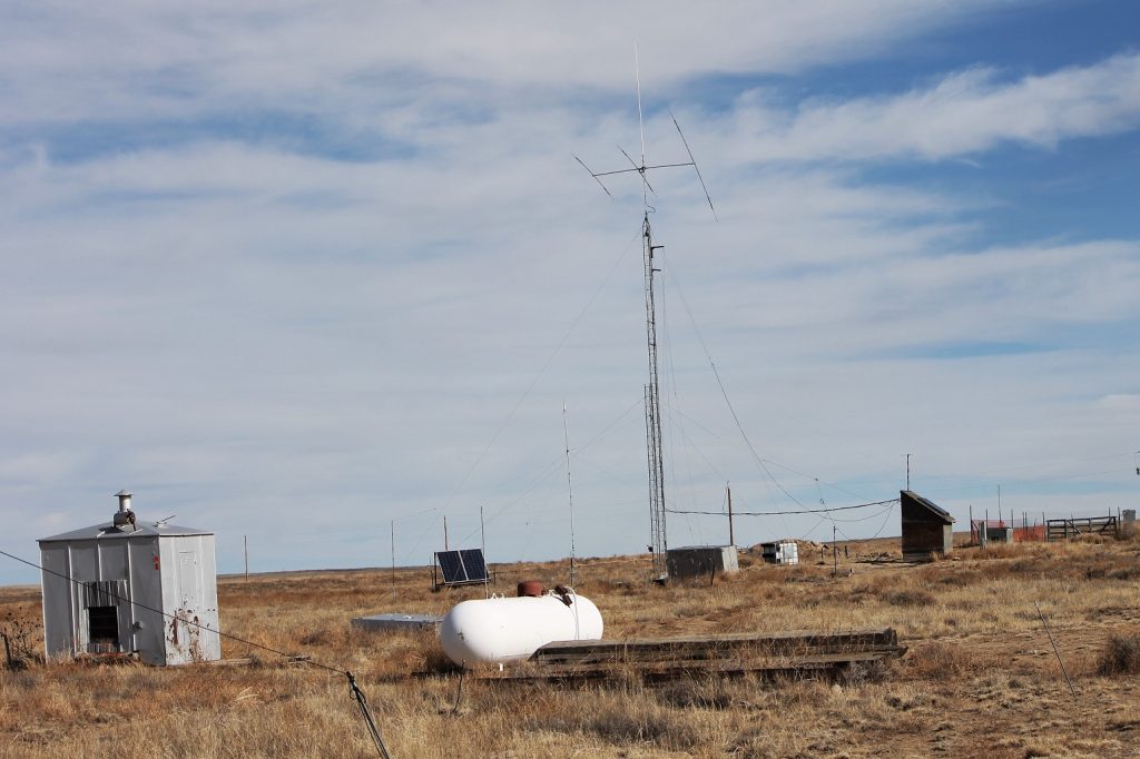
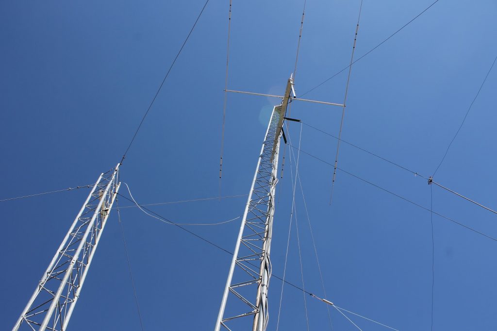
Science Lead Rich Russel (seated) and System 1 Lead Glenn Davis setting up the pulsar observations. Bill Miller, Lewis Putnam, Rich Russel, and Glenn Davis in the Communications Operations Trailer during the observation runs.The display for the System 1 manual tracking. The circles in the black field represent the antenna beam width for different frequencies. The large blue ring represents a 4 degree diameter beam width, and is for the 408 MHz feed currently being used for the pulsar observing. The inner yellow ring is 0.8 degrees in diameter, which is for our HI hydrogen observing at 1.4 GHz. The pink dot represents where the center of the beam is pointing. A star field map is projected on the background black field. The upper part of the display shows azimuth and elevation of the antenna, and its conversion to the celestial coordinates of Right Ascension and Declination at the current time.The signal strength across the frequency spectrum being observed. For pulsar observing, we cannot detect the pulsar signal itself in real time. We must integrate the signal over at least a half hour of observing. Then we process the signal, with an expected pulsar timing. That process averages out the background noise while adding the actual pulsar signal enough to elevate above the noise floor — in theory. The 60 foot dish antenna turning to aim at the pulsar.The 408 MHz antenna feed. Ray Unberecken has designed a base for the antenna feeds so that these can be easily swiveled out for service and changeout. Ray designed and built this feed.
2. Bob Haggart worked on completing the building of desk and shelf space in the Communications Operations Trailer. The additional space is actually important, as that gives us a means to organize and better utilize our work space, and not instead have items pile up randomly.
Bob HaggartNew desk and shelf space in the Communications Operations Trailer.New desk and shelf space in the Communications Operations Trailer. Note the addition of amenities, of microwave oven and coffee pots.
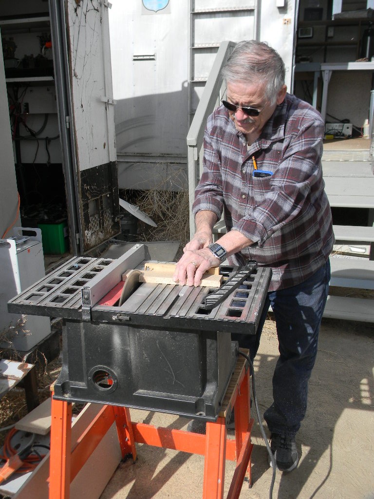
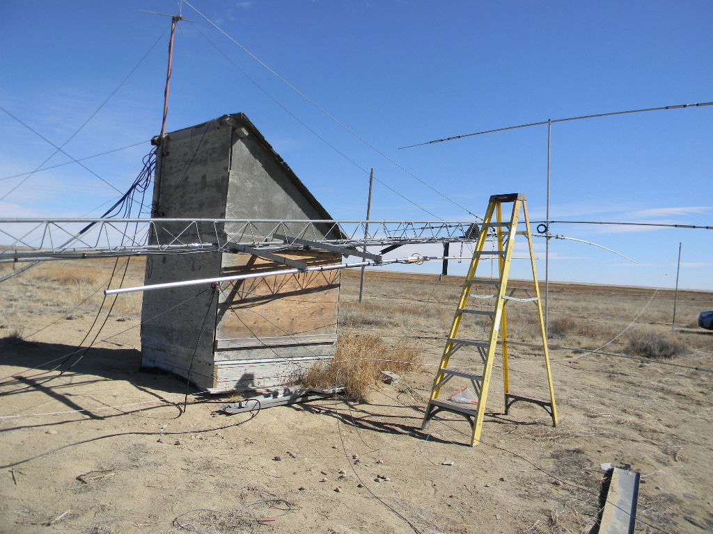
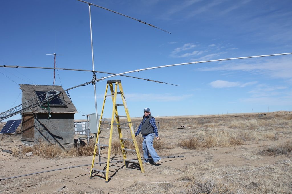
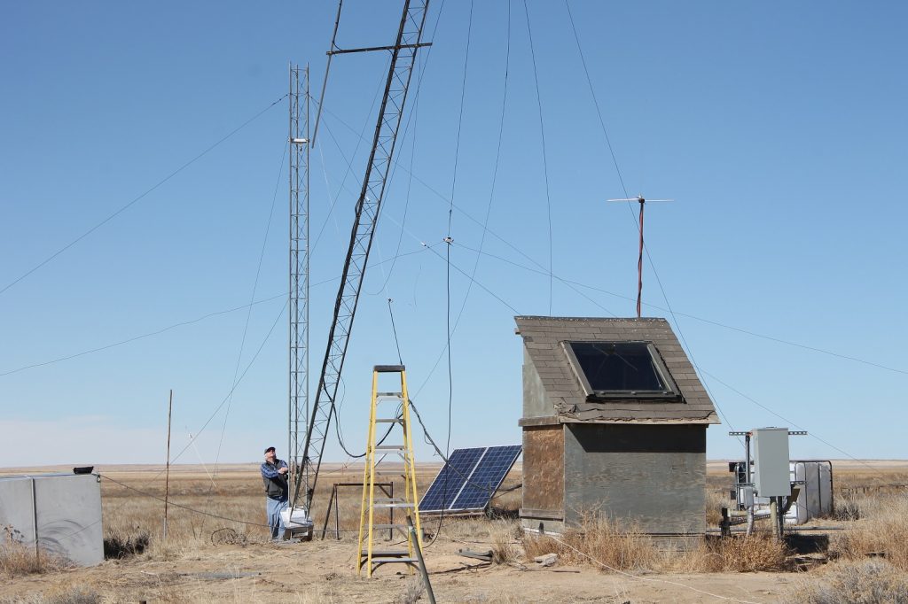
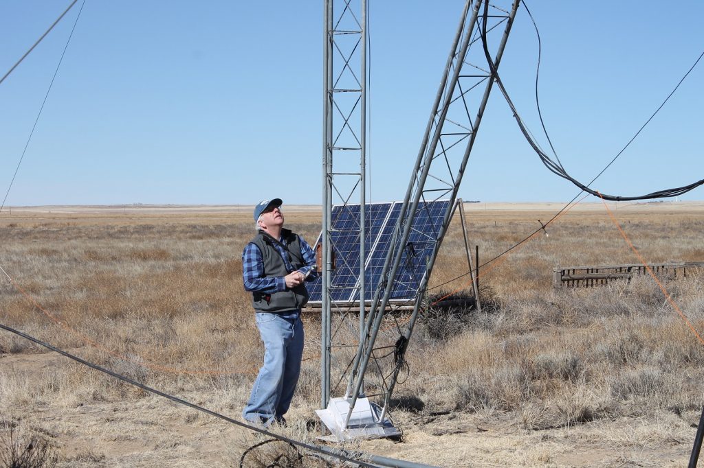
3. A third project was the repair of the front element of the 3-band Yagi ham radio antenna on the 40-foot tower. The front element had rotated slightly askew.
The front element of the 3-band Yagi ham radio antenna on the 40-foot tower rotated askew somehow. Fixing this was our third project undertaken this day.The tower was rotated down for service.Bill Miller aligning the front element. Also working on this were Gary and Bob. Bob utilized cable lengths to help ensure actual evenness. We also used squares and levels. Gary working on the antenna. The ladder was used to access and retighten the center supports at the mast. While the tower was down for the service, Bill reinforced the structural support for the 2-meter band vertical antenna on a side support from the tower.Gary raised the tower back up.The 50-foot tower almost at its vertical position.
After the tower was raised back to vertical position, Bill and Gary slightly rearranged the positioning of the 80 meter dipole that is supported from a pulley on the tower. The repositioning separated the dipole with better clearance from other nearby wires
We discovered that the Communications Trailer phone used for our 2-meter talk-in radio was transmitting but not receiving. Bill started to troubleshoot it.Bill photographing the dish antenna. Pikes Peak is visible in the distance, over a hundred miles away.Gary also photographed the dish antenna.The 60 foot antenna rotating back to its parking position after the observing runs.
Rich Russel processed the observation data, but the processing did not bring out the pulsar. Troubleshooting is a topic at the February Science Meeting. Meanwhile, the System 1 antenna pointing system worked well.
The group finished up the work well before sunset, so that traveling back with the sun setting was not a significant issue. We had good weather for this trip, for a winter day in February. Our temperature was in the 40s F, which was actually midler than the 30s in Colorado Springs. And our wind was light.
This autumn Dr. Richard Russel attended the Very Large Array (VLA) Imaging course in Socorro, New Mexico. The course taught how to take the data sets from multiple large interferometer antenna systems and produce images and science statistics.. This post presents the slides from the DSES Science Meeting on November 25, 2019. This is an update from Dr. Russel’s posts on the topic from October 19 and 31.
Dr. Russel also presents his September 2019 results of Hydrogen 21 cm (HI) drift scan measurements at his newly installed 9-foot dish antenna at his home in Colorado Springs.
Please click the link to view the illustrated pdf file:
Recently Dr. Richard Russel attended the Very Large Array (VLA) Imaging course in Socorro, New Mexico. The course taught how to take the data sets from multiple large interferometer antenna systems and produce images and science statistics.. This post is an update from Dr. Russel’s post on this topic on October 19.
In this post, Dr. Russel also presents initial results of Hydrogen 21 cm (HI) drift scan measurements at his newly installed 9-foot dish antenna at his home in Colorado Springs.
Please click the link to view the illustrated post:
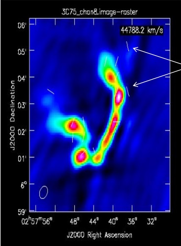
Recently Dr. Richard Russel attended the Very Large Array (VLA) Imaging course in Socorro, New Mexico. This course taught how to take the data sets from the VLA archive and produce images. The following is the first set of images reduced from the VLA archive by Dr. Russel.
Images were made of these astronomical objects:
3C75 Binary Black Hole System
3C391 Supernova Remnant
Asymptotic Giant Branch (AGB) Star IRC+10216
MG0414+0534 Gravitational Lens HI Absorption Line
Each image takes about 1 day to produce from the raw observation.
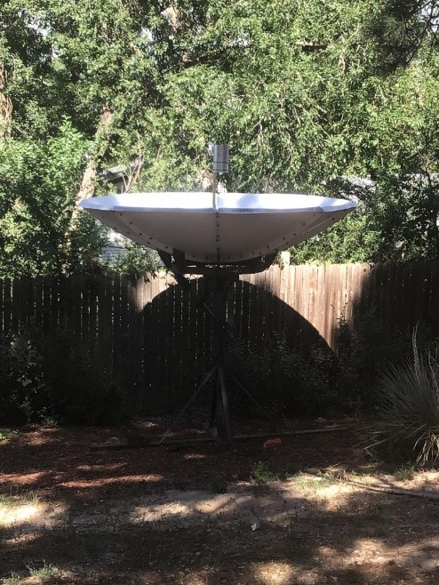
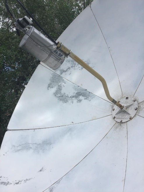
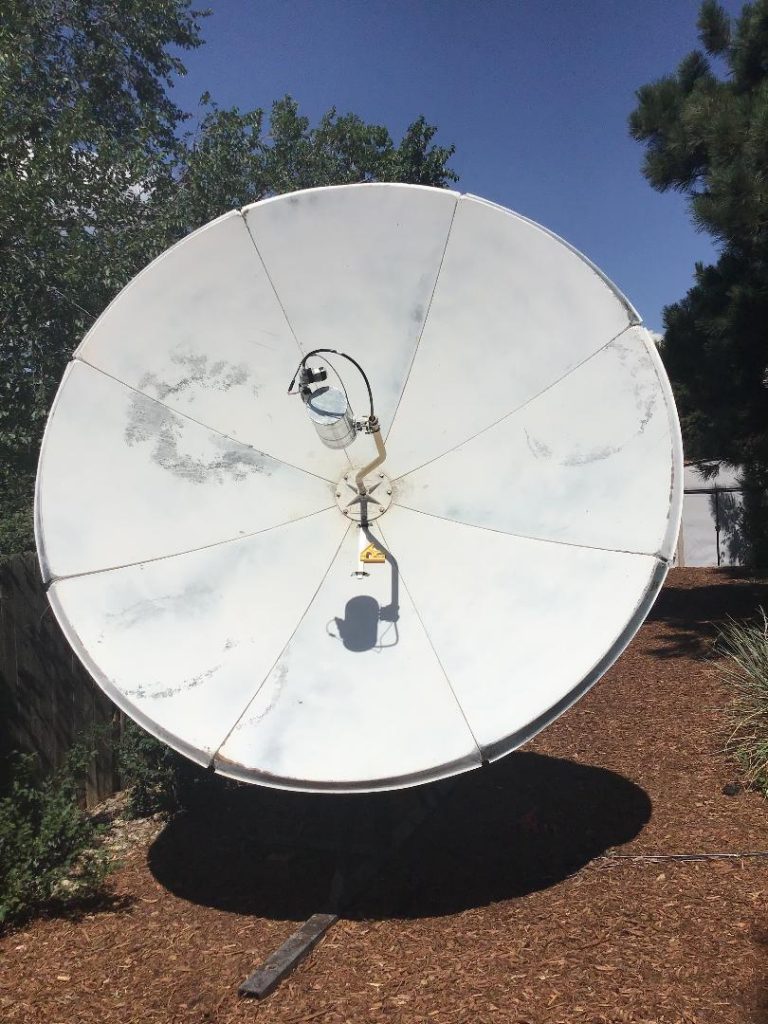
The DSES 9-foot dish is operational at Dr. Russel’s house in Colorado Springs. It is outfitted with a 1420 MHz feed with 2 low-noise amplifiers with over 40 dBi of gain and a noise figure of 0.35. The receiving system is a Spectracyber 1.
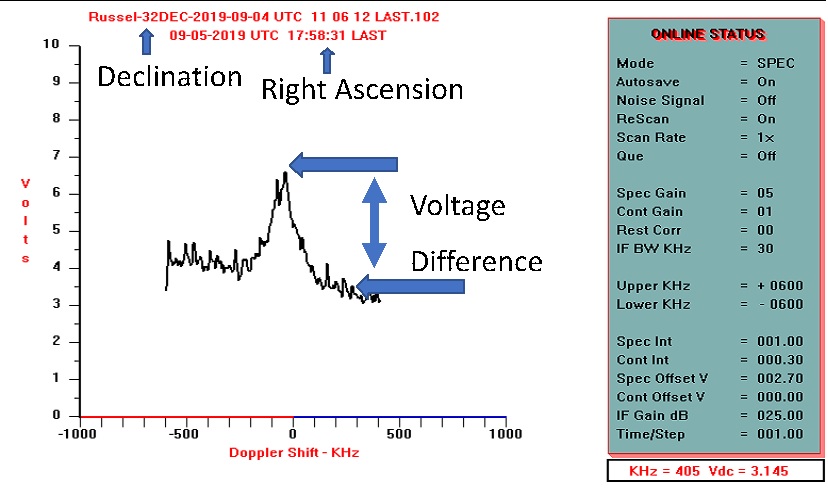
The output of the Spectracyber shows the relative peaks of hydrogen with a corresponding Doppler measurement.
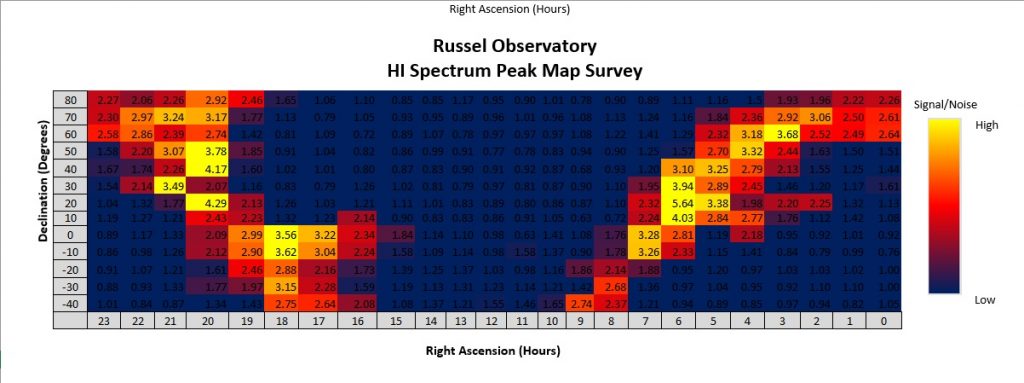
Dr. Russel performed a drift scan of the visible sky and plotted the relative peak hydrogen signals.
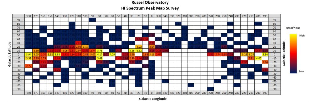
The hydrogen maps very well
to the visible Milky Way. The plot below converts the Celestial Coordinates
into Galactic Coordinates. Note that the peak hydrogen is concentrated near the
0 Galactic Latitude.
Special
Thanks to Ray Uberecken and Steve Plock for helping to set up the system.
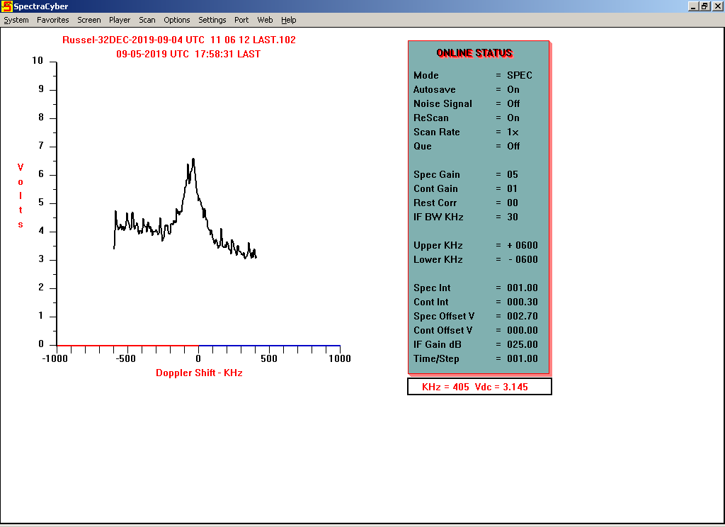
Ray Uberecken came over today with another LNA, which we put in series with the first LNA. This did the trick and overcame our cable loss problem. I conducted a small drift scan across the galactic center at -32 Declination. Here is a quick result.
I will spend the next couple of days fine tuning the azimuth pointing and weatherizing the LNAs.
I will forward information to allow certain members teamviewer access if they want.
Thanks Ray and Steve Plock for their technical support!!
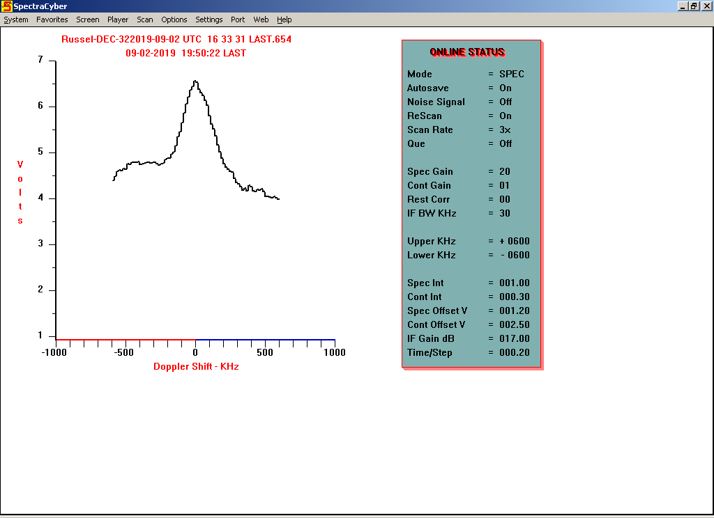
Part 2 – September 4, 2019
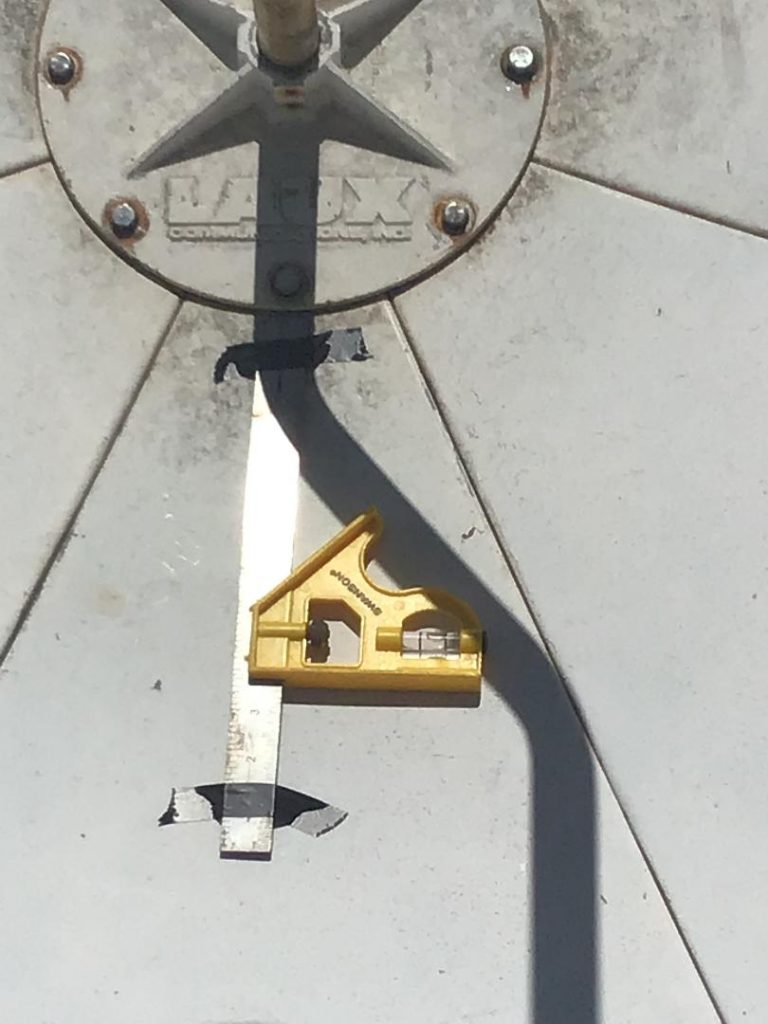
The 9 ft dish at Dr. Russel’s house is operational! It is set up to collect neutral hydrogen frequencies at 1420.406MHz. Today the dish azimuth was aligned using the Sun and a level.
The receiver is a Spectracyber 1 from Radio Astronomy Supplies. Below is the measurement of the hydrogen spectrum near the galactic center. RA 17hr 58min DEC -32 degrees
Training on the use of the system will be conducted at the science meetings.
This is Skip Crilly‘s updated paper/presentation, “Radio Search for Extraterrestrial Intelligence SETI is fun ! Geographically-spaced Synchronized Signal Detection System“, updated July 2019. Skip presented it at the Society of Amateur Radio Astronomers conference at Greenbank, WV on August 4, 2019. The link will open as a pdf file.
Abstract: Radio Frequency Interference (RFI) is a confounding problem in radio SETI, as false positives are introduced into receiver signals. Various methods exist to attempt to excise suspected RFI, with a possibility that true positives are rejected, and that un-excised RFI remain as false positives. Uncertain far side-lobe antenna patterns add to the uncertainty. To ameliorate the RFI problem, a system having geographically-spaced simultaneous and synchronized reception has been implemented. A radio telescope at the Green Bank Observatory in Green Bank, West Virginia has been combined with a radio telescope of the Deep Space Exploration Society, near Haswell, Colorado to implement a spatial filter having a thrice-Moon-distance transmitter rejection. Approximately 135 hours of simultaneous synchronized pulse observations have been captured from November 2017 through February 2019. This presentation describes the problem, observation system, observed results and a proposed hypothesis to be subjected to attempts at refutation through further experimentation and RFI and ETI transmitter signal model development.
Two wave audio files from the presentation, “Tones” and “Slow Tones”: