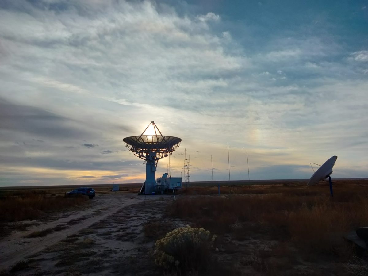
Glenn Davis and Dan Layne made observations for pulsars at our Haswell antenna site this week, on Tuesday November 1, 2022. They successfully observed for the first time pulsar B1556 -44, making this the 23rd pulsar DSES has observed to date.
The PDF files in this post are their observation and data report, and an updated list of pulsars detected by DSES to date.
Photos courtesy of Glenn Davis. Text by Bill Miller.
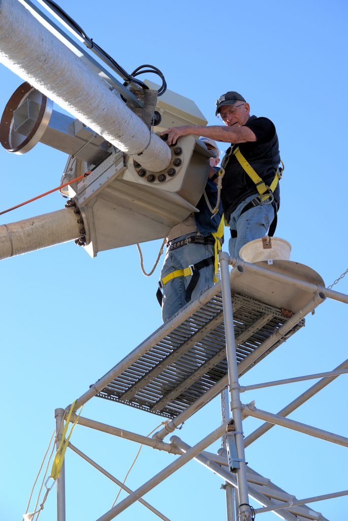
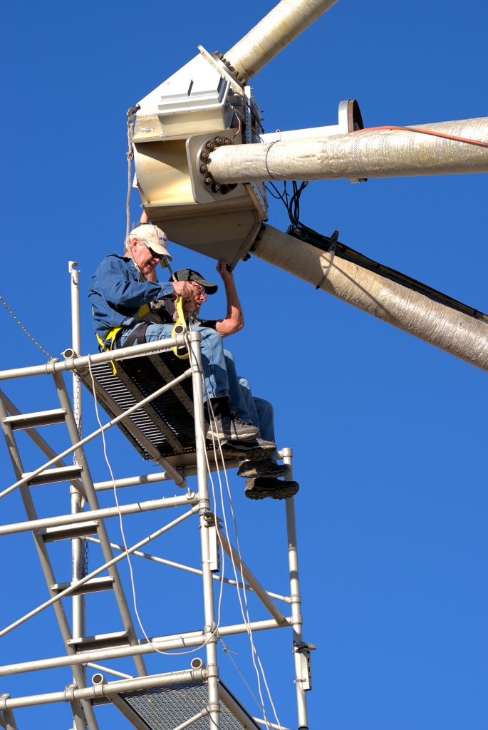
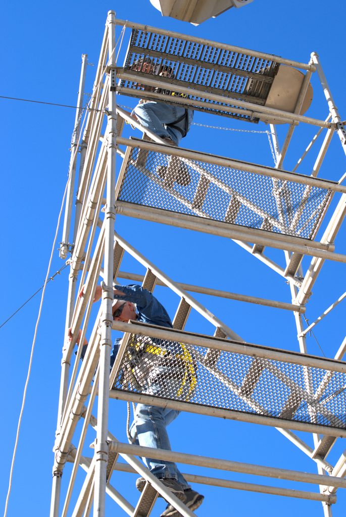
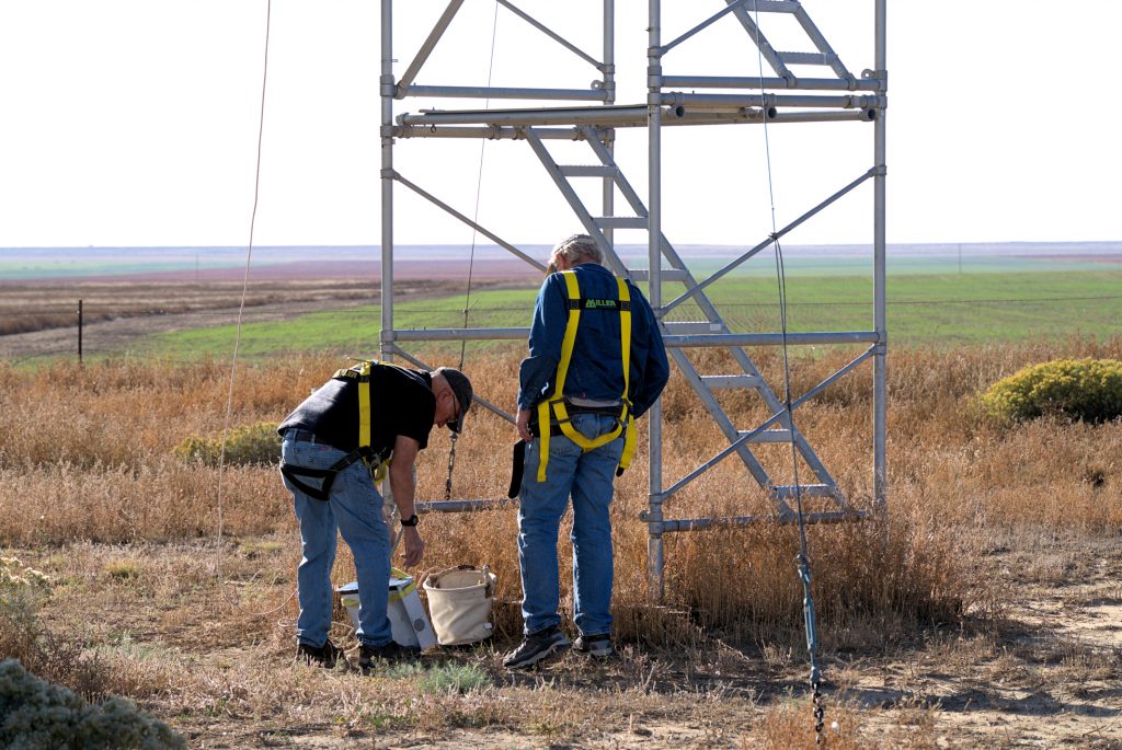
On Friday afternoon October 14, 2022, we prepared the 60-foot dish antenna for the weekend’s Moonbounce communications operations in the ARRL EME contest.
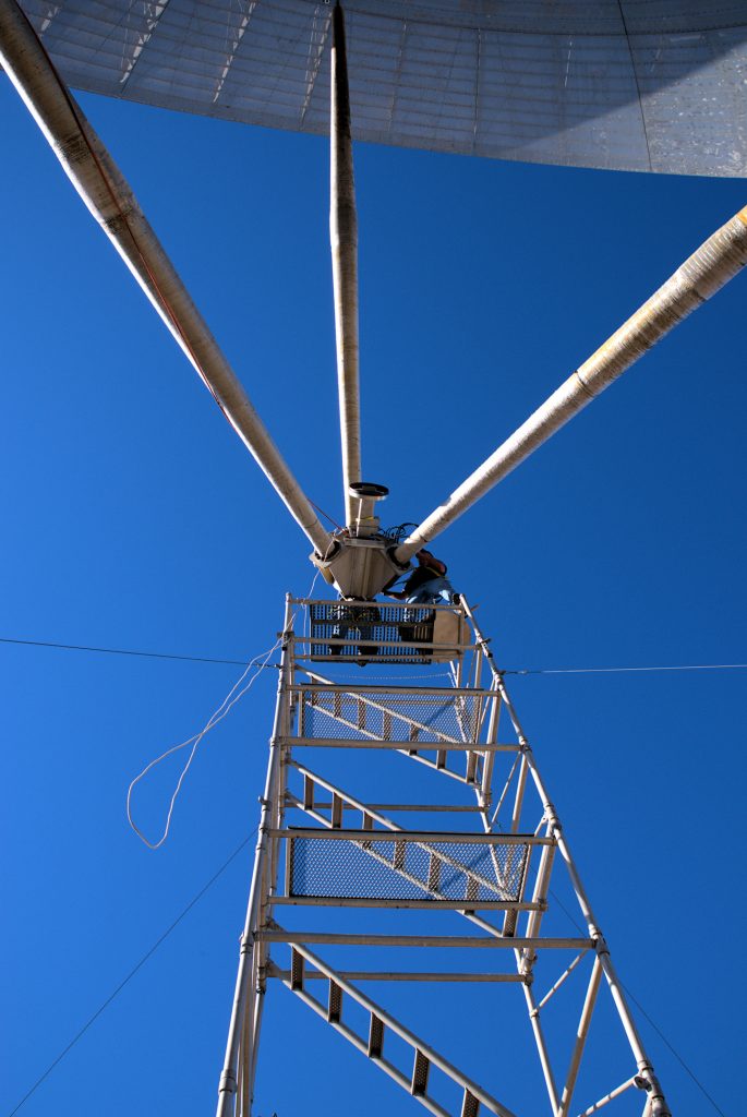
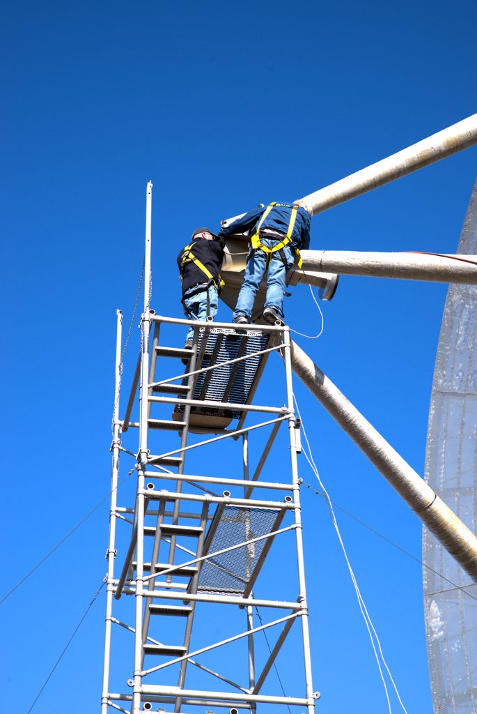
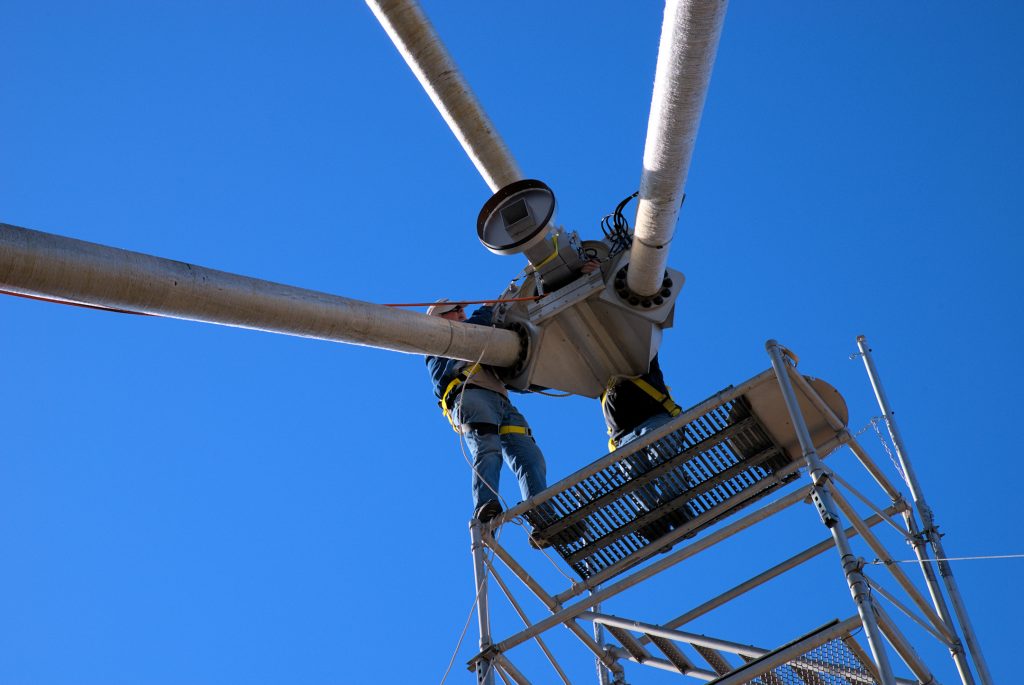
Glen Davis updated the tracking software, checked the callibration of the mount and helped as ground crew and photographer. Meanwhile Ray Uberecken and Bill Miller climbed the scaffold and changed the feed from the 437 Mhz antenna to the 1296Mhz antenna. They also installed Ray’s 180 watt amplifier at the antenna feed point and checked the system reception from Ray’s Calhan residence beacon.
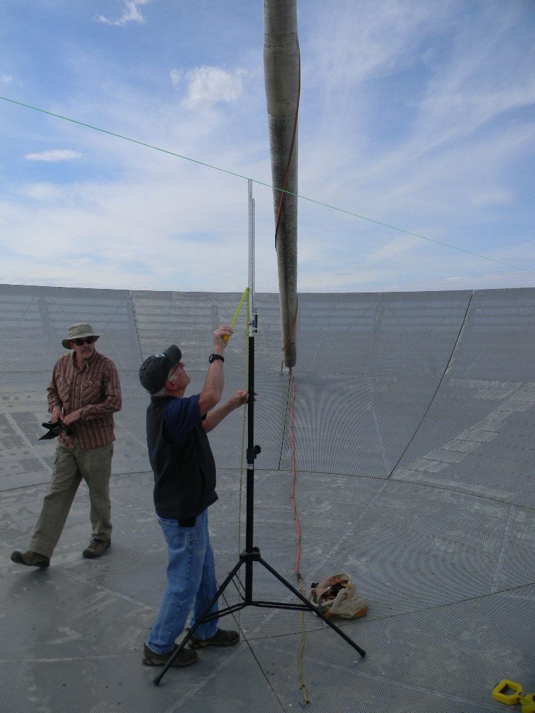
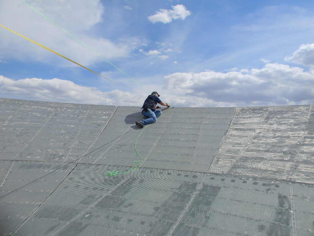
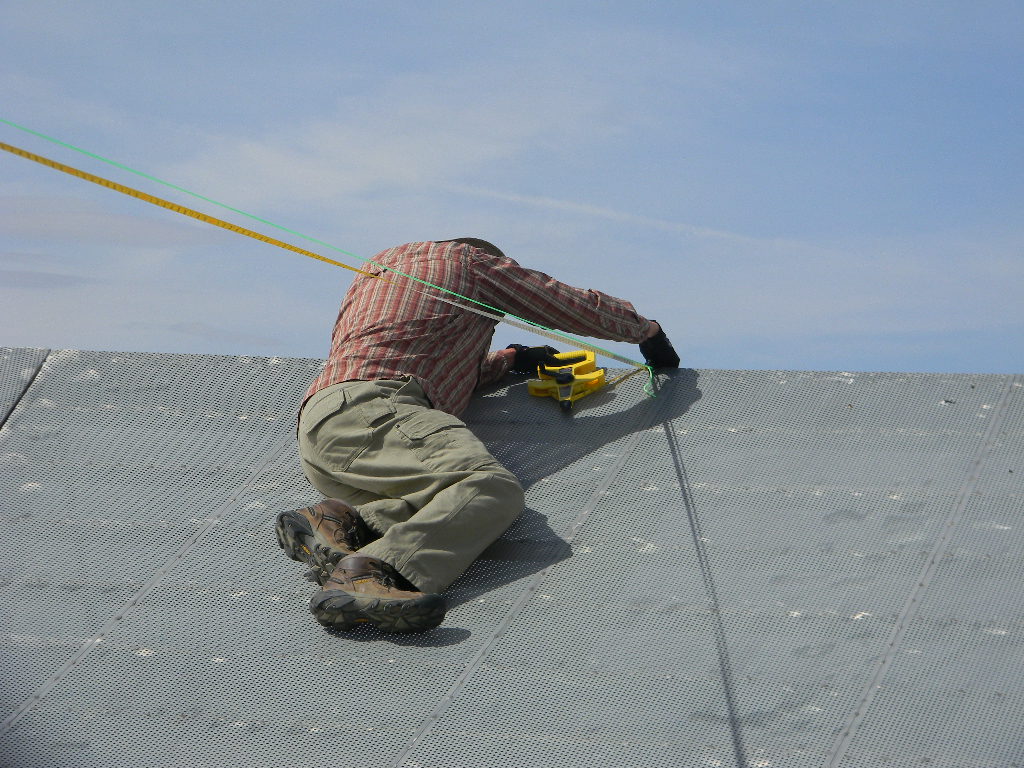
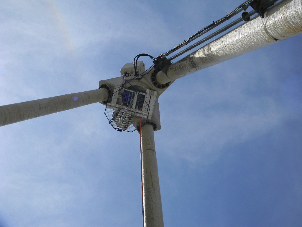
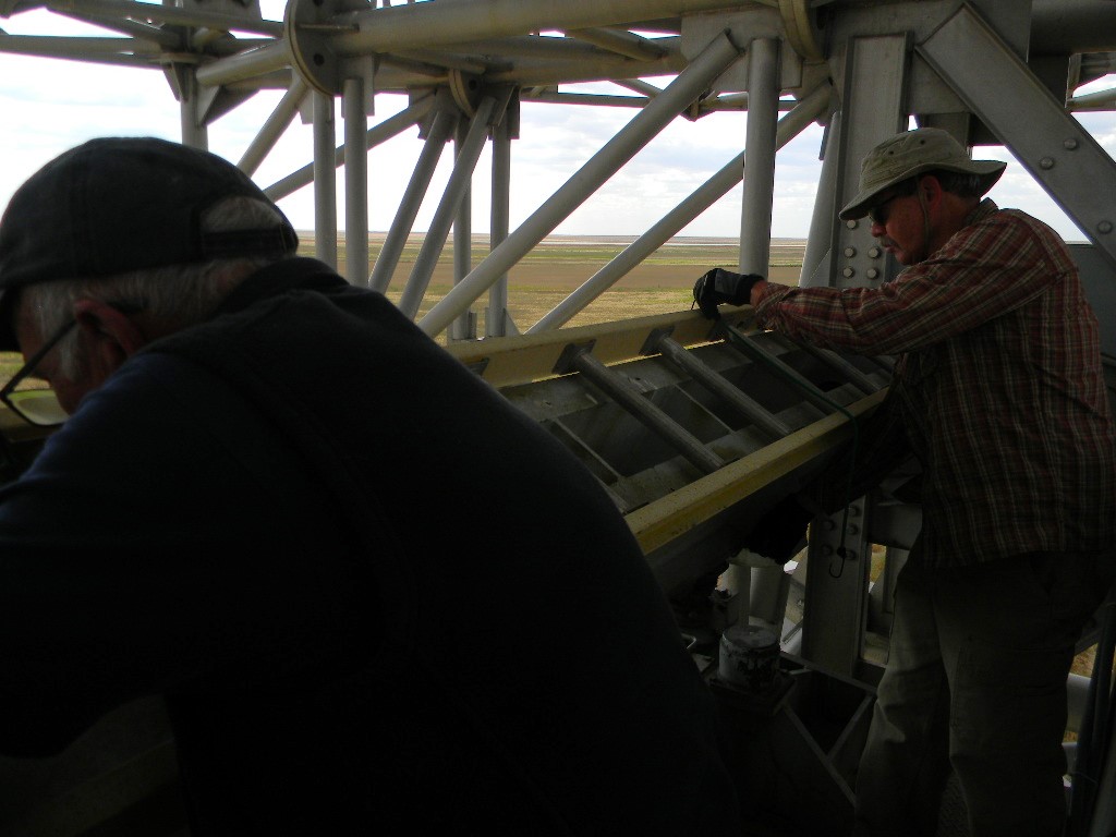
On Sunday October 2, 2022 Ray Uberecken, Dan Layne and Gary Agranat climbed on to the 60-foot dish antenna to measure the dish diameter, the distance from the dish center to the feed, and the bore alignment. This verified the original geometry specifications continue to be valid to at least within a quarter of an inch.
The original plan for the day was to also install the 1296 MHz feed at the focus, for the upcoming ARRL EME contest. However, the wind gusts increased, as was anticipated from the forecast. The feed changeout was therefore postponed.
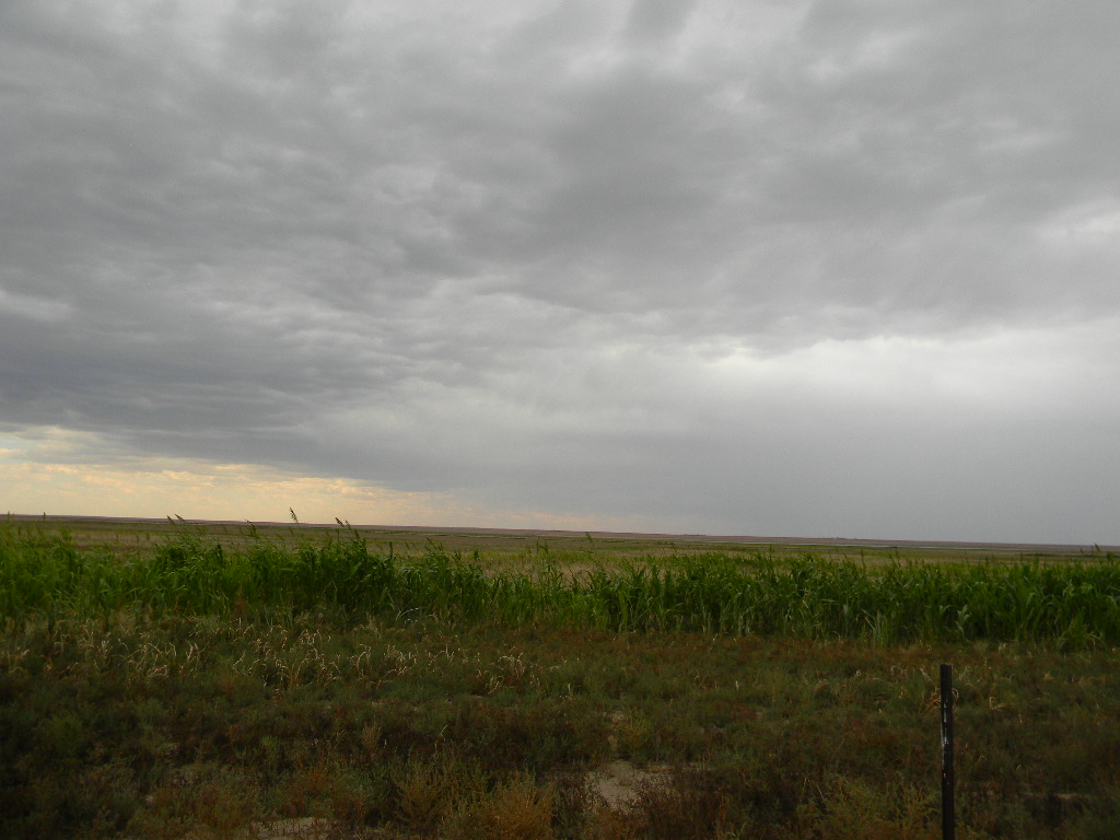
Measuring the first leg of the distance from the dish center to height of the edge, using the tape measure suspended from the dish edges.Ray securing the tape measure to measure the dish diameter.Dan measuring the dish diameter at the opposite edge.Antenna focusSecuring the ladderScattered rain shafts started to pass during the afternoon.
Deep Space Exploration Society will support the Japanese OMOTENASHI Cube Sat Moon lander, by attempting to receive and record its UHF downlink signals enroute to the Moon and after landing. OMOTENASHI is a project created by the Japanese space agency JAXA Amateur Radio Club, and is one of ten Cube Sat satellites on the NASAArtemis 1 lunar mission.
Several hours after Artemis 1 boosts from an Earth parking orbit to a transfer orbit to the Moon, OMOTENASHI should deploy. After 6 days the OMOTENASHI will separate into an orbiter and lander, and the lander will make a hard landing on the Moon. The lander is designed to survive and then transmit signals.
This was our most successful EME season to date, not just in the number of contacts we made, but in the participation of our members, in successfully using a digital mode for many contacts for the first time, and with our equipment working well with no trouble. And we are learning from our experiences.
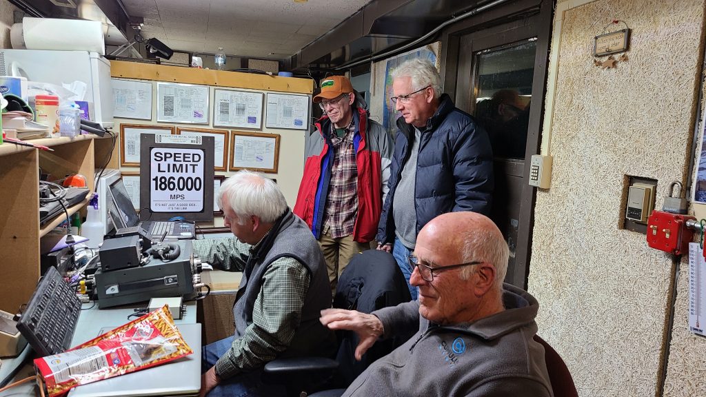
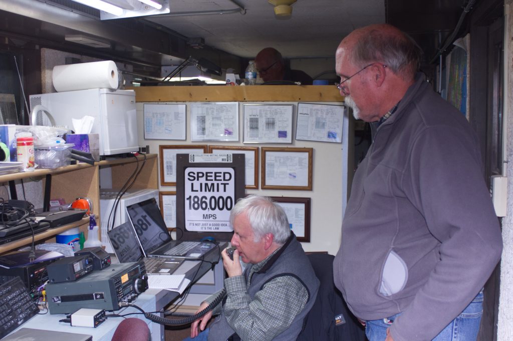
For our December weekend we had Gary Agranat WA2JQZ and Ray Uberecken AA0L operate through the whole weekend. We also had Jim Burnett WB0GMR, Flyod Glick WD0CUJ, Bill Miller KC0FHN, Glenn Davis, and Marc Stover. Jim got his first experience operating EME, making some of the digital Q65 contacts Friday night. Floyd, Bill, and Glenn stayed Friday night. Marc was there both nights to make time lapse movies of the antenna tracking the Moon. Glenn ensured our tracking system was working well. Everyone had a chance to call CQ on SSB and to hear their voices reflect back from the Moon 2 seconds later.
Moon bounce is communicating by sending signals to the Moon, and reflecting those signals back to Earth to anyone else who has visibility of the Moon and the necessary equipment. With the Moon’s distance a quarter of a million miles away, traveling at the speed of light, the signals take about 2 seconds to make the round trip journey. And the signals are significantly weakened by traveling that long a distance. With the Moon traveling at a different velocity from one’s location on the surface of the Earth, there also is a Doppler shift to compensate for. Moon bounce communications therefore can be quite a technical challenge. Reliably copying the weak signals can also be a challenge. With our large 60-foot dish antenna, our group is fortunate to have an excellent capability to meet all these challenges.
Because Moonrise was at about the time of sunset (as it was on the November weekend), our EME operation was essentially all over night, with a short period available also after sunrise.
We operated on the 23 cm band (1296 Mhz). We operated Morse Code CW, SSB voice, and Q65 digital mode. More about our technical setup later.
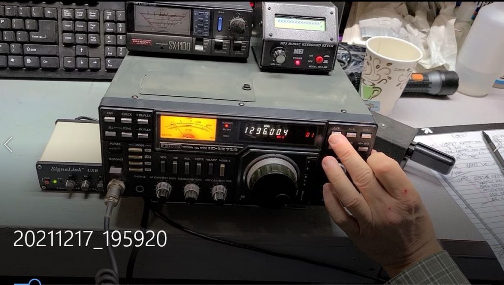
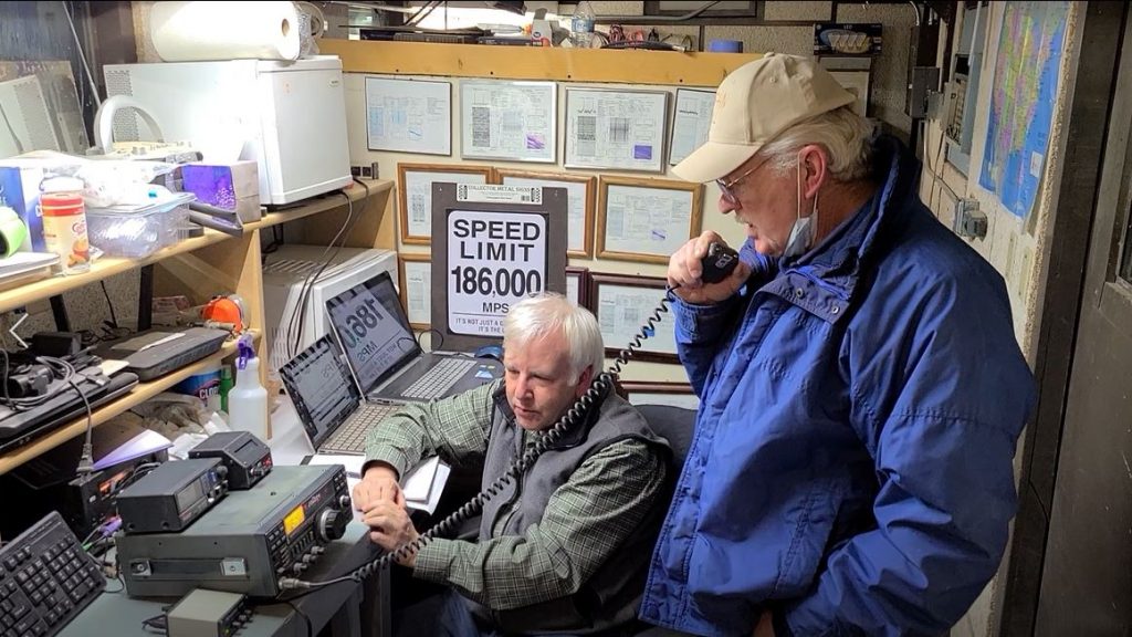
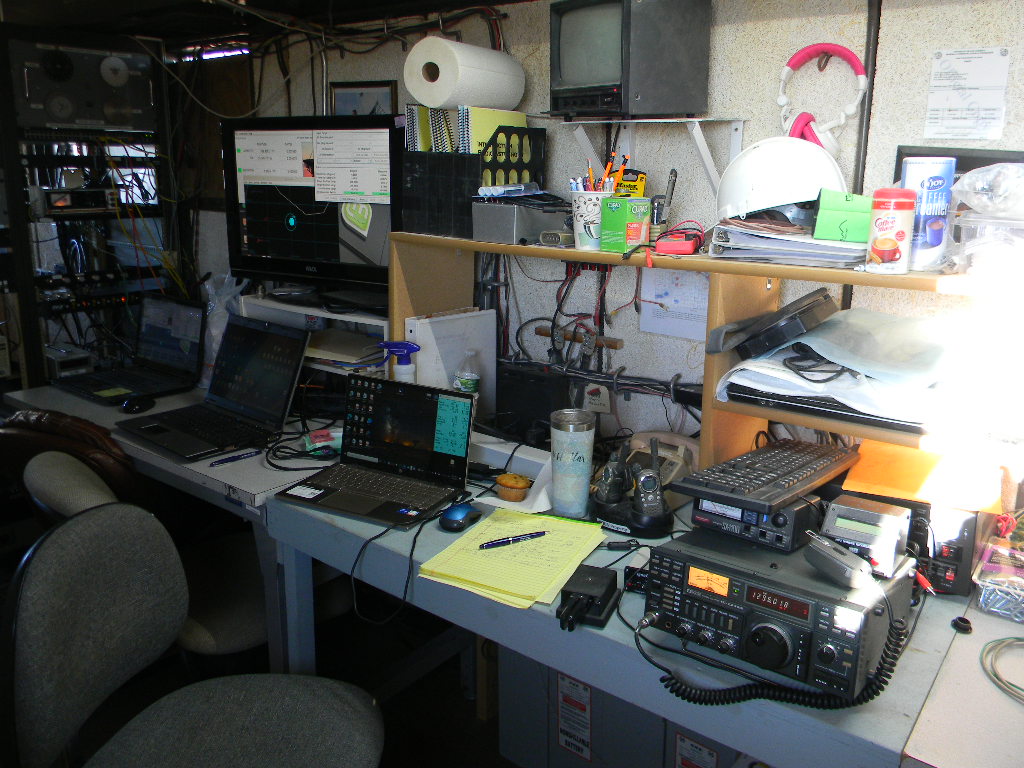
Friday evening, the Moon rose shortly before the 0000 UTC contest start time. We pointed our 60-foot antenna to the Moon and started tracking as we waited. (Photo by Gary Agranat WA2JQZ)Moonrise Friday evening (Photo by Gary WA2JQZ)Our operation setup in the trailer. Our transceiver was an ICOM IC-1275A. We sent Morse Code CW with a keyer set to 16 words per minute. (The keyboard could also be used for sending Morse Code, but that wasn’t used.) Antenna tracking was set and monitored with the computer and display at left. We monitored our signal output with the power supply meter and scope display located in the rack further left. The laptop at right was used for logging. Off to the right a separate laptop was used to control making the digital Q65 contacts.
On our December weekend we made 47 EME contacts. Added to our November weekend operation, that brought the total number of contacts to 92. This compares with the 50 contacts we made for the contest last year.
Of the 92 contacts, 54 were CW (Morse Code), 2 were SSB phone, and 36 were in the new Q65 digital mode. 53 contacts were to Europe, 33 to North America, 3 to South America, 1 to Australia, 1 to the Philippines, and 1 to Asia (Japan). We contacted 22 unique DXCC entities, 16 states, and 3 Canadian provinces.
For the November weekend, Dan Layne AD0CY got our Q65 digital mode working and made 2 contacts then. On the December weekend, Jim WB0GMR operated Friday night and made 8 Q65 contacts. Gary WA2JQZ stayed for the operations on both weekends and made the other contacts (CW, SSB, and Q65) with the help of Ray AA0L.
For this year’s contest we experienced no significant technical problems. That enabled us to start operating as soon as the contest time started and as soon as we had a signal path to the Moon. The operations for both weekends went smoothly and with a relaxed tone.
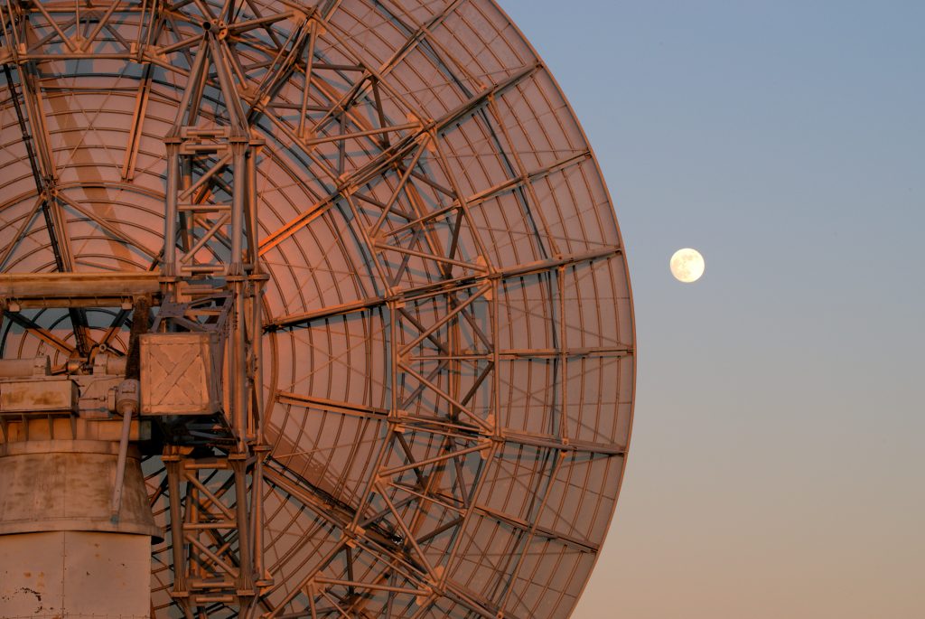
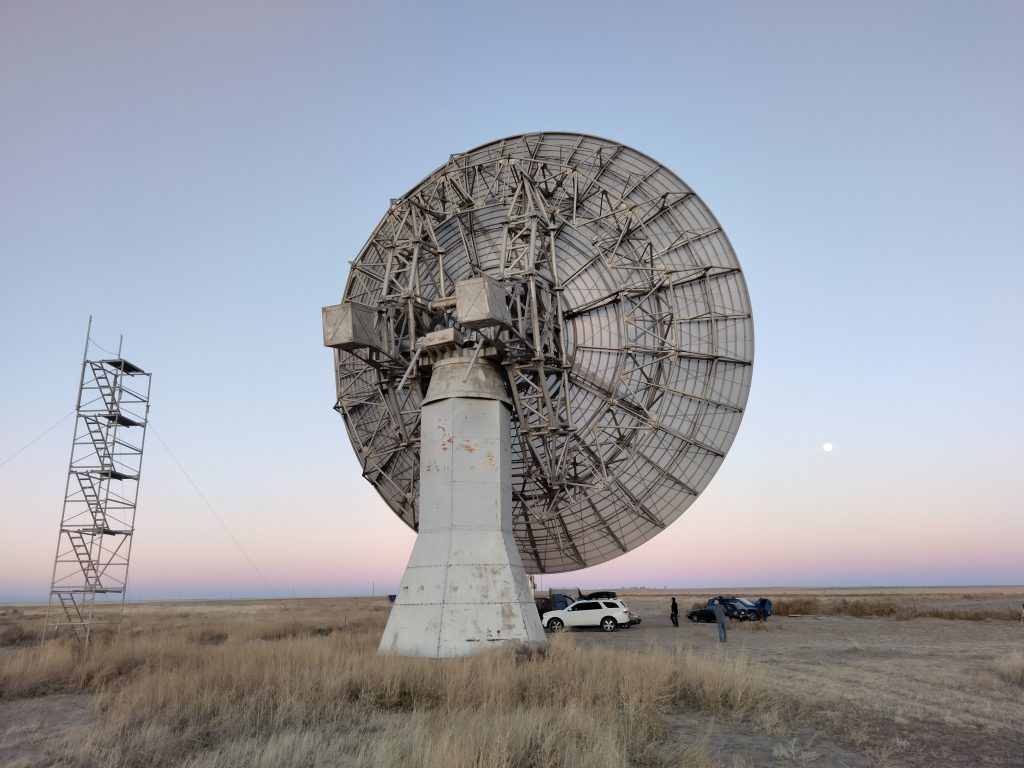
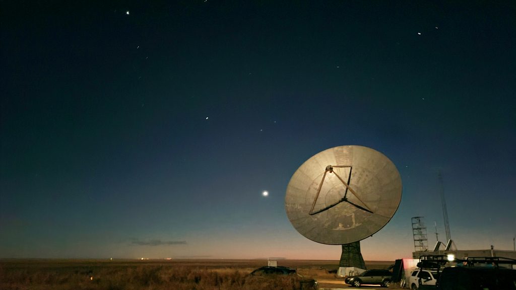
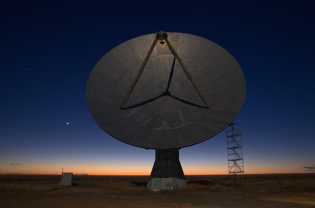
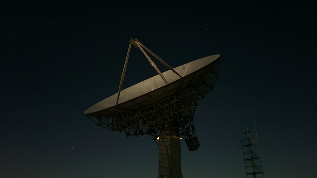
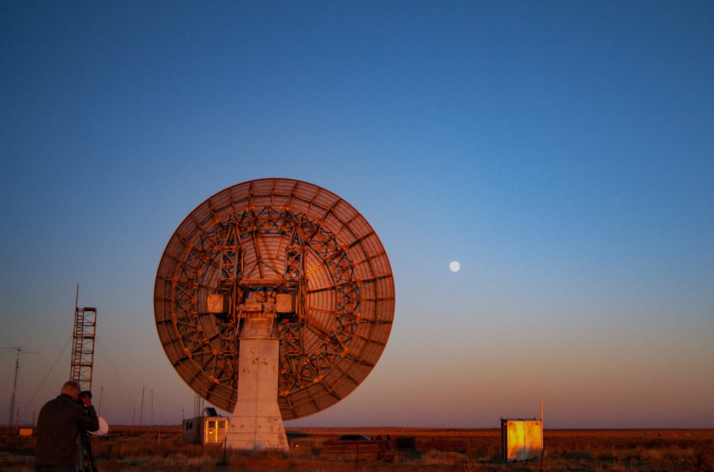
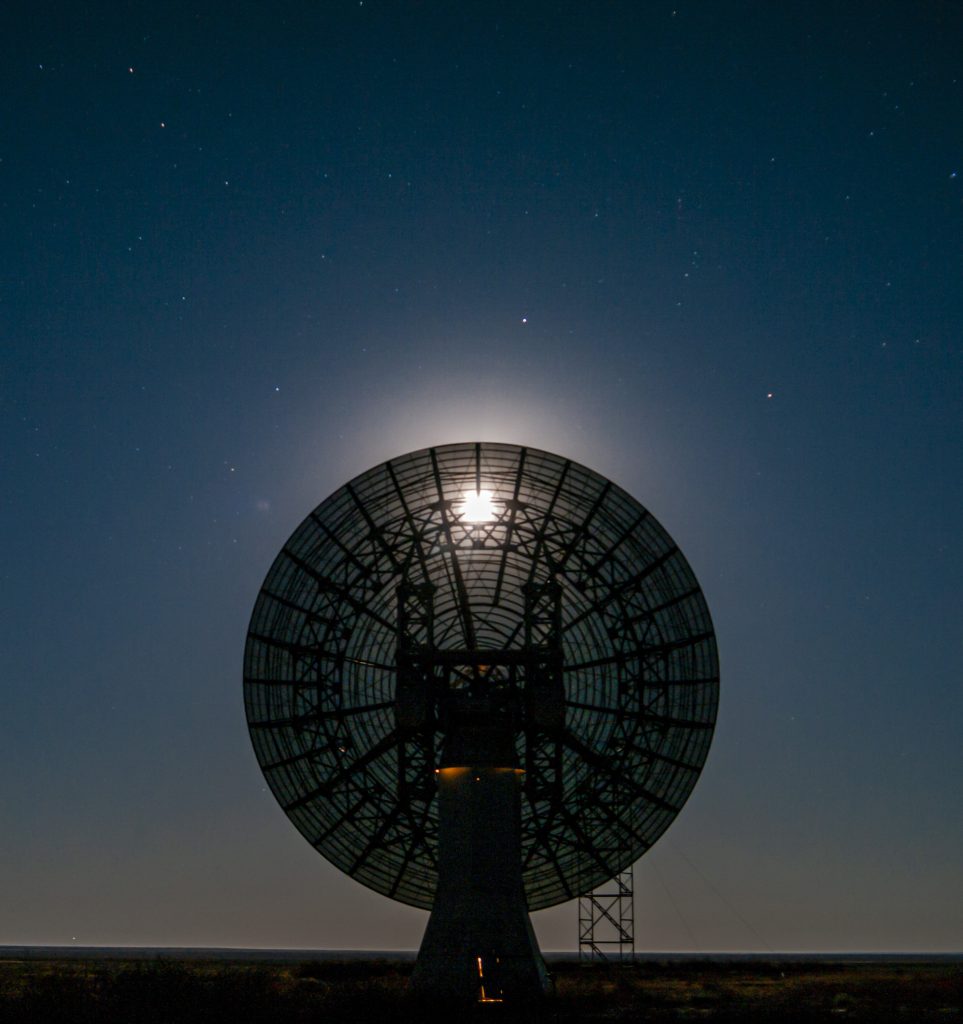
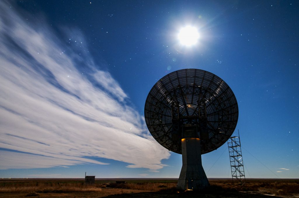
Our 60-foot dish antenna bathed in full moon light as it tracked the Moon during operation Friday night. The planets Venus, Saturn, and Jupiter (lower center to upper left) brightly lit the western sky after sunset. (Photo by Bill Miller KC0FHN)Our 60-foot antenna tracking the Moon. (Photo by Glenn Davis)
Ray AA0L contributed this technical description: The moonbounce equipment this year consists of an ICOM IC-1271A with a built-in low noise preamp (about 1 dB), a VHF Design 150 Watt amplifier at the feed, a Tokyo High Power intermediate power amp with built in Gasfet preamp, VHF Design .3 dB nf, 30 dB gain preamp at the feed and a KL6M feed with a choke. All this provides a noise figure of 0.4 dB with an overall gain at the feed of >40 dB. We have more than sufficient gain in both directions to overcome the 200 or so feet of feedline from the trailer to the dish feed.
Our 60-foot antenna tracking the Moon Friday night. (Photo by Bill Miller)
On Friday night we tried to get in as much Morse Code CW contacts as we could. We switched to digital Q65 when we had contacted most of the CW contacts we could hear at a given time. Through the night we alternated back and forth. We also occasionally attempted SSB voice.
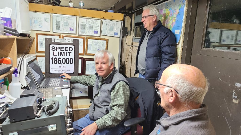
Gary copying Morse Code CW during a contact, with (L to R) Floyd Glick, Glenn Davis, and Ray Uberecken. (Photo by Bill Miller) Due to the Doppler shift, we had a gap between transmit and receive frequency by as much as 3 KHz. We switched between the two frequencies by using the transceiver’s two VFOs. We used the WSJT software by (W1JT Joe Taylor) to continually calculate and display the frequency difference. (Still from a video by Bill Miller)Jim WB0GMR (standing) and Gary WA2JQZ operating SSB. Jim later operated digital Q65 and made 8 contacts. (Photo by Floyd Glick)Bill Miller KC0FHN calling CQ.
On Saturday morning we determined when the Moon would rise in Japan and in Australia. We stayed awake for that, and when those times came, we searched for those stations. That’s how we immediately found our Japan and Australian contacts, as soon as they had a signal path. We got them in time before the pileups that followed. When we couldn’t hear any additional stations, we went to sleep.
We had an unexpected power failure late Saturday morning, after the Moon had set and we were taking a break. The cause was eventually traced to a pigeon that had short circuited the transformer where the electric power comes into the site. We called the local utility, and after a couple of hours they reset the circuit breaker on the main county road. This was unfortunate for the pigeon. But fortunately for us this didn’t happen during our EME operation, and didn’t disrupt us.
As we anticipated, most of the stations we heard on CW on Sunday night were ones we had already worked. Therefore on Sunday night we concentrated most of our efforts on digital Q65. We made most of our digital contacts then.
Gary, Glenn, and Ray. Digital Q65 operating. (Photo by Bill Miller)
On Sunday morning after the Moon had set, as we woke up and wound down and had coffee, Gary made some HF FT-8 digital contacts on the 15 and 20 meter bands. A portable multi-band end fed antenna was extended from the trailer to the service tower. And the contacts were made on a Yaesu FT-950. The bands were open to as far as Europe and Japan. This gave us a chance to get on the air on the more traditional ham bands, and to be part of the rest of the ham radio community. Over 50 FT-8 contacts were made.
The Yaesu FT-950 operating HF FT-8 and the End fed antenna extended to the service tower. (Photos by Gary Agranat)
This was our most successful EME operation to date. We made more contacts, our equipment worked well as expected, we had increased participation, we developed our experience further, and we all enjoyed the experience. Certainly hearing one’s voice or signal come back from the Moon 2 seconds later is an experience one doesn’t forget. This should give us a basis for doing more EME operations, better, and more times than just for the contest.
This year several members also devoted their efforts to photographing. Marc Stover’s time lapse movie work and Floyd Glick’s lunar photography follow.
Mark Stover devoted all of Friday and Saturday nights to record time lapse movies of our dish antenna tracking the Moon, from Moonrise to Moonset. He used several cameras, capturing several perspectives, and several aspects of the antenna’s and sky’s motions. These are still images from photographing. These are followed by a one-minute movie he edited together. The temperature both nights dropped to the teens F. Marc wore an exposure suit to keep warm.
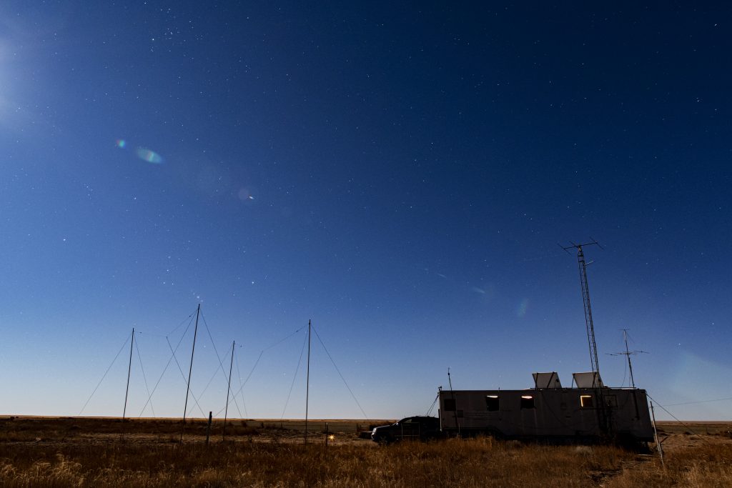
MoonriseOur operations trailer K0PRT at night. The constellation Orion is rising in the southeast.Moonset with the antenna tracking.A still-image from Mark’s movie, as the Moon nears the western horizon before dawn, with the antenna precisely tracking it. The constellation Orion is to the left of the Moon. The tight Pleiades cluster is to the right. The Moon itself is in front of the constellation Taurus.
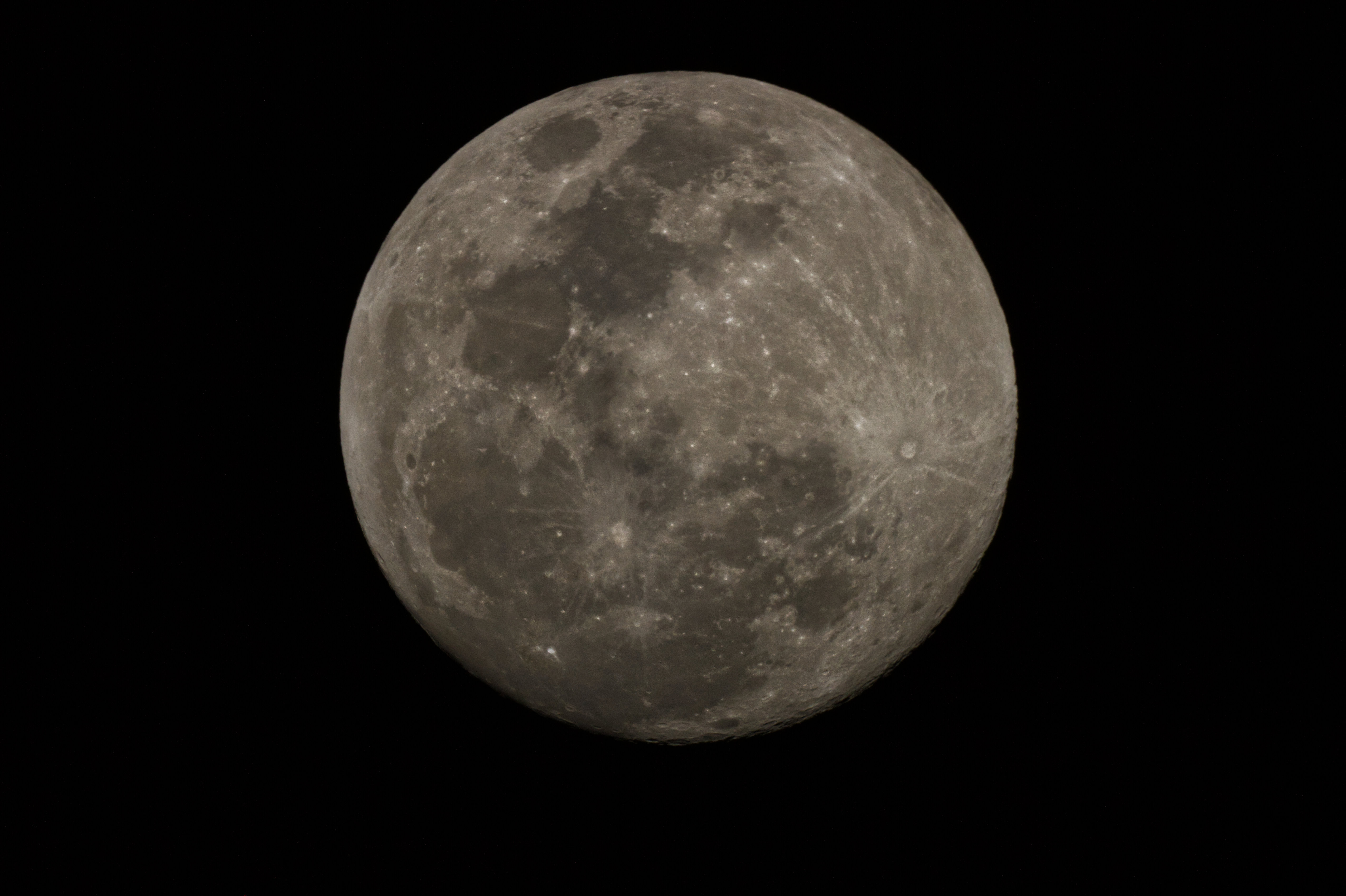
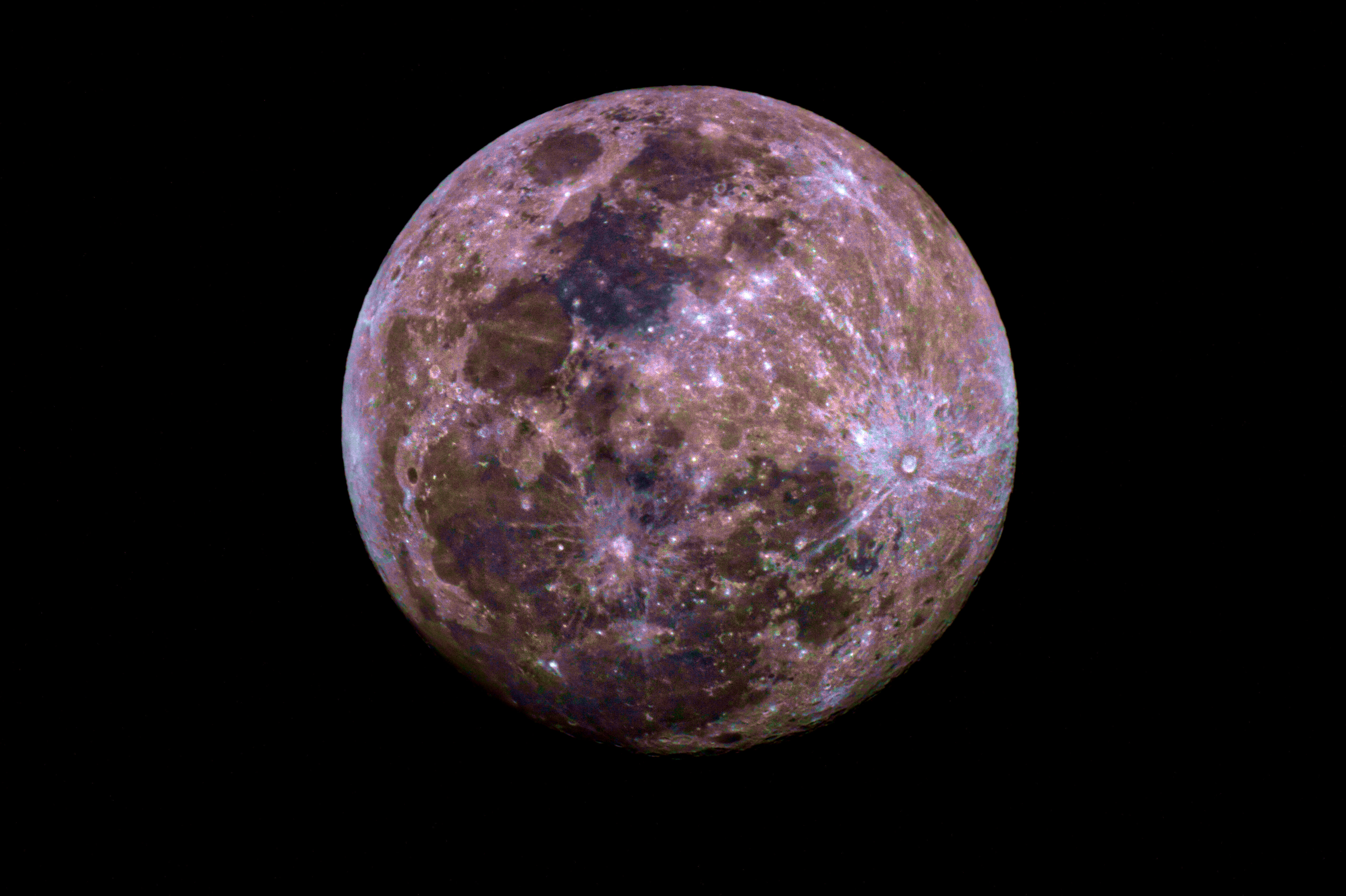
Floyd Glick (WD0CUJ) took these astronomical color images of the Moon on Friday night. He took these unfiltered images through his 5 inch Maksutov telescope (unguided). Floyd wrote: “The Moon actually has color, but because it is so bright our eyes perceive it as black and white. I have enhanced the colors (solar temperature = 5900K) in the last picture to illustrate them better.”
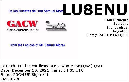
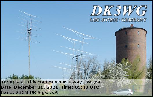
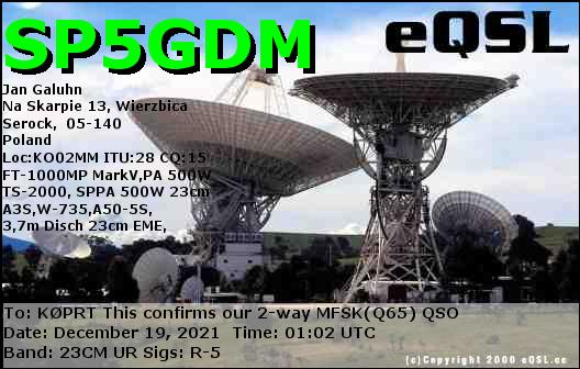
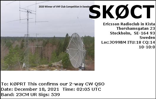
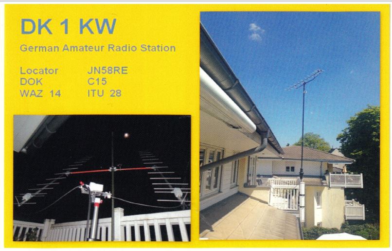
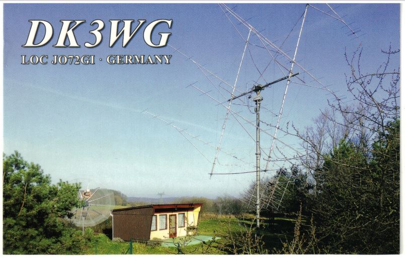
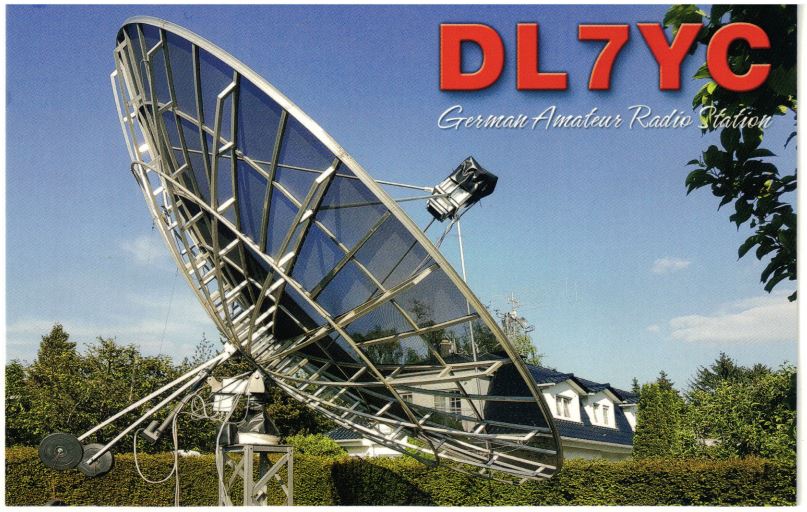
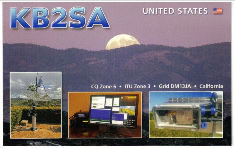
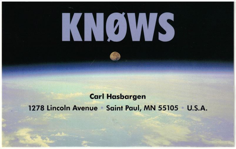
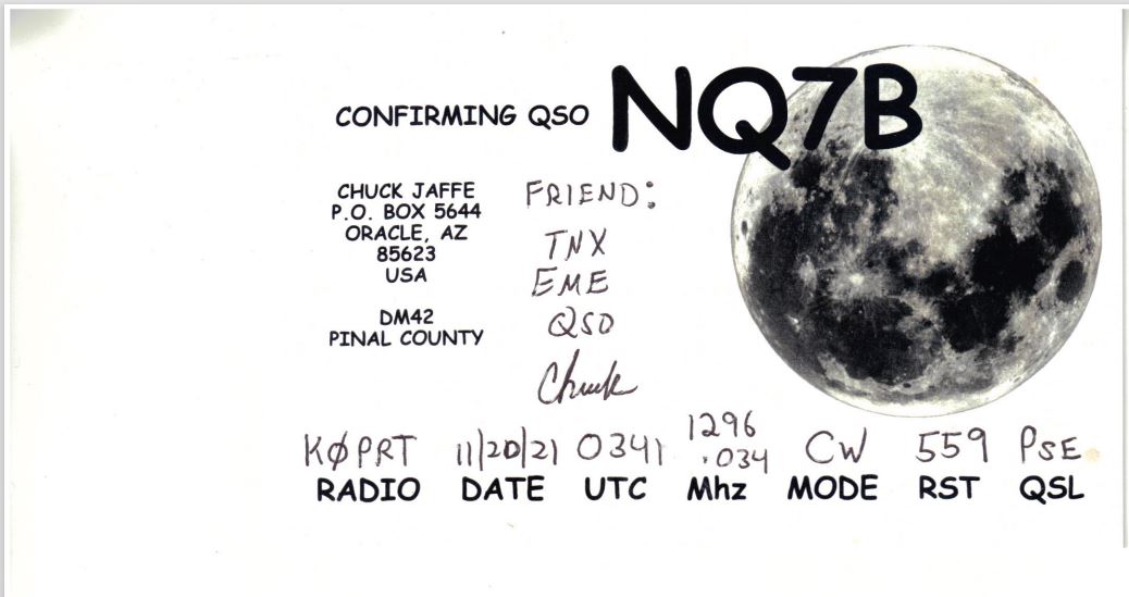
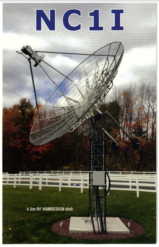
QSL confirmation cards we received for our EME contacts, by eQSL and post office mail. Countries represented are Argentina, Chile, Germany, The Netherlands, Poland, Romania, Sweden, and the United States:
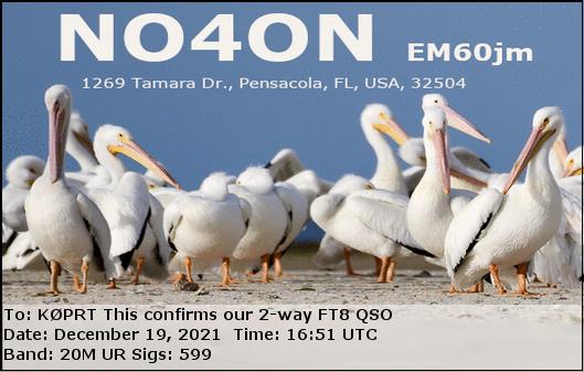
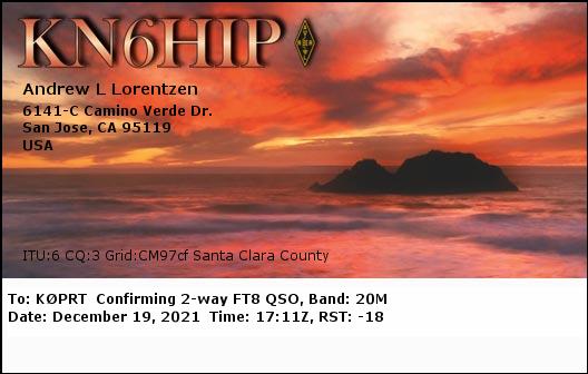
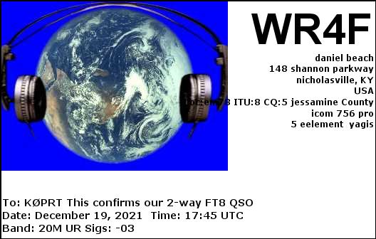
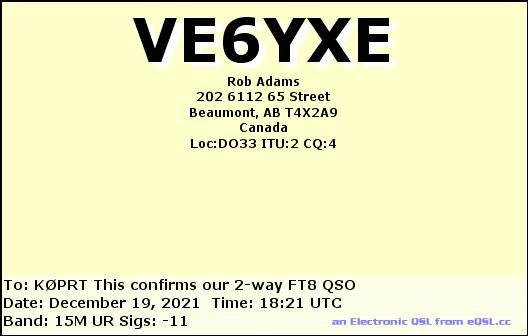
Some of the variety of QSL cards we received for our high frequency (HF) FT-8 digital contacts from Sunday morning, on the 15 and 20 meter bands. We reached North and South America, Europe, Asia, and Africa:
This past weekend our radio telescope group DSES successfully operated EME (Earth Moon Earth) Moon bounce communications again. EME Moon bounce is transmitting and directing signals to reflect off of the Moon, about 240,000 miles away in space, and communicate with anyone else on Earth who has the Moon visible above their horizon and who has similarly capable equipment. As we did last year, we participated in the ARRL annual EME contest. We used our restored 60-foot dish antenna, operating at 1296 MHz, with our call sign K0PRT. This turned out to be our smoothest and most successful EME operation to date.
We can only communicate sending signals off of the Moon when the Moon is above our horizon. For this past weekend the Moon was just past full, which means the Moon rose just after sunset, and set shortly after sunrise. That means we could only operate during the night time — all-nighter operations.
Ray Uberecken (AA0L) and Gary Agranat (WA2JQZ) were the primary team on the site operating for the full weekend. Marc Stover was on site all of Friday night, taking time-lapse night photography of the dish antenna as it tracked the Moon, with the starry sky moving as the Earth rotated. Our science lead Dan Layne (AD0CY) was on site on Saturday afternoon and evening. He particularly helped us properly configure our digital mode, and he succeeded in making Q65 digital contacts to South American and Europe. Both Marc and Dan also got some experience calling CQ on SSB voice, and they heard their voice signals traveling at the speed of light reflected back about 2 seconds later.
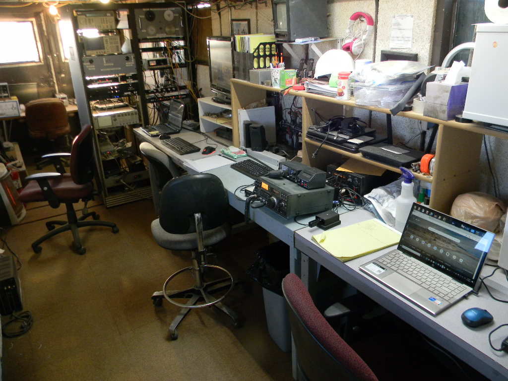
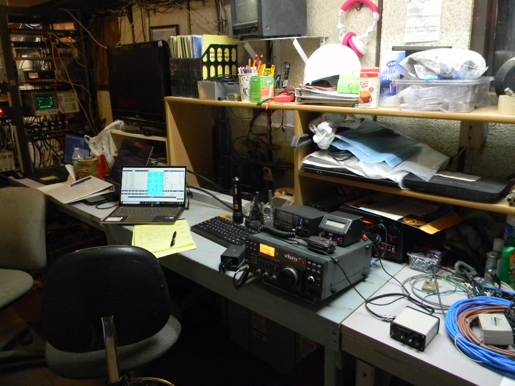
Our set up overnight Friday. We used an ICOM transceiver transmitting 150 Watts. A Morse Code keyer was attached, set to 15 words per minute (WPM). The keyer device was also able to send code by typing characters on the keyboard, but we kept to sending the standard way. This is my preference (Gary), yet this also enables flexibility to adjust one’s sending as one hears the conditions. We also used the microphone for SSB voice. On Saturday night, in addition, we tried the Q65 digital mode, using the Signalink box to the right of the transceiver, connected to a laptop. Another laptop to the left of the keyboard kept our contact log digitally. It was also set up with a WSJT 10 program, to display to us the needed Doppler shift between our transmit and receive frequencies, to correct for the difference in speed between our site and the Moon. When we transmitted, we monitored the green oscilloscope and power supply on the rack at left, to verify we in fact were sending out a signal to the antenna.
This was our most successful weekend EME Moon bounce operation to date. We made 19 contacts the first night, and 26 contacts the second. (In comparison, last year for the first weekend of the contest we made about 25 contacts, and we operated then for just one night.) Just about all of our equipment worked perfectly and smoothly. 42 of our contacts were by using Morse Code. Dan made our two Q65 digital mode contacts: to IK7EZN in Italy and CX2SC in Uruguay (our only South American contact). Our other contact was using SSB voice (with DL6SH in Germany). EME voice communications requires better equipment capability and often also more power, so making EME voice contacts is generally rarer.
Almost all of our contacts were done between Moonrise and about 1 AM local time, on each of the two nights. We had a moon path to Europe until about that time. By then Ray and I (Gary) were feeling tired enough, and the European signals were becoming sparse. We were aware that in another hour or so Japan should have moonrise and give us a communications path to us. But we decided getting some sleep was more important, and we chose to sleep. We woke again around sunrise and went back on the air, with the Moon then to the west over the Pacific Ocean. On Saturday that enabled us to work DU3T in the Philippines, and VA7MM in British Columbia, Canada. We heard DU3T work an Australian station, but we didn’t hear the Australian station ourselves. We tried calling CQ ourselves, but didn’t hear anyone else. On Sunday morning we didn’t succeed in contacting anyone — we suspected we might not find anyone by then, but we believed the try was still worth it. (By comparison, last year once the Moon gave us a path across the Pacific, we were able to work 2 stations in Japan and one in Australia.)
On our second night we made contact with our DSES member VE6BGT Skip Macaulay in Alberta, Canada.
With our 60-foot antenna we are probably one of the stronger and more capable stations on the air. We consistently got strong signal reports from other stations. I typically got RST reports of 579. Most of the stations I gave signal reports to had much lower values, from 219 to 569. We were outputting about 150 Watts.
As an indication of our good signal, on Saturday night I had a run of 18 Morse Code (CW) contacts in a row, in a period of about an hour and a half. That is, after I completed one contact, I heard someone else trying to contact me, and I then continued with them. This kept happening for 18 contacts straight. In ham radio terminology this is called a “pile up”. This is fun and uplifting when it happens. But it also takes endurance and energy and patience.
Often the signals we heard were extremely weak. And so there is definitely some skill to bring to bear. Depending on conditions, I may need to repeat key parts of the message many times. For Morse Code CW I may need to adjust the speed of my sending to a rate and pattern that I think the other person can copy. By choosing how I send, I indicate to the other person how I am hearing him or her, and that person can then adjust to my conditions too. It helps to be mindful too, so that one doesn’t make the other person feel intimidated. We are trying to make successful contacts, we also are part of a community.
Of our total 45 contacts, 28 (the majority) were with Europe. Those were with Germany (DG5CST, DL6SH, DL7UDA, DF3RU, and DL0SHF), Poland (SP6JLW, SP7DCS, SP9VFD, SP6ITF, and SP3XBO), Sweden (SK0CT, SM5DGX, SM6FHZ, SM7FWZ, and SM4IVE), Czech Republic (OK1KKD, OK1CA, OK1CS, and OK2DL), Italy (IK2DDR, IK3COJ, and IK7EZN), France (F5KUG and F6KRK), England (G4CCH and G3LTF), Finland (OH2DG), and European Russia (RA3EC). 12 contacts were with the continental US: WA9FWD (WI), N8CQ (NC), NQ7B twice (AZ), WK9P (IN), N5BF (CA), WA6PY (CA), WB8HRW (OH), W2BYP(NY), K2UYH (NJ), K3WM (PA), and W6YX (Stanford University, CA), plus one with Alaska (KL6M). 2 were with Canada: VE6BGT (AB), and VA7MM (BC). Plus we had the digital contact with Uruguay CX2SC. And DU3T in the Philippines.
***
I’ll mention, during the daylight hours on Saturday, while we had some quiet time in between Moon passes, Ray and I each spent some time with other activities. Ray did some autumn cleaning of the operations trailer. That included reorganizing the rack equipment, to make it easier for our current needs, and removing cables not in use. Ray also switched our cable for receiving GPS to an antenna on the roof, from the portable antenna we had been using inside.
Meanwhile I went to operate our HF (High Frequency) ham radio station at the bunker. I had not been on site for over a year. I wanted to check that our HF equipment and antennas were still functioning Okay. Starting around 1 PM local time I made some casual SSB contacts with our multiband vertical antenna and our directional 3-element Yagi antenna on the 50-foot tower, on the 20 and 15 meter bands. Most of those contacts were Parks on the Air stations around the country. I contacted NB6GC as well, the USS Hornet Museum ship in Alameda, CA (Bay Area) for a special event commemorating the splashdown of Apollo 12. The operator there noticed our callsign for DSES, and he told me he would be operating EME that evening too, though I think on a lower frequency. I also tried going on the 40 meter band with the vertical, but I mostly heard regular weekend nets, and I didn’t want to interfere with those. Starting at 2 PM local I then operated on the ARRL November Sweepstakes SSB contest. I chose to stay mostly on the 15 meter band with the Yagi, as 15 meters seemed more relaxed than 20 meters, and we had good propagation to the US northeast. I also swung the antenna around to contact stations I heard in California and Washington State. I sometimes searched around the band, I sometimes held a frequency and called CQ. Later I did try 20 meters too. In all I made 57 contacts, to 32 of the 84 ARRL sections in the US and Canada. Besides getting on the air and testing our equipment, I was interested to have our club station with our callsign participate with the rest of the ham community, so that other hams get to know us and to feel us as part of their community. I operated on HF for about 2 hours, though not all at once.
The one maintenance issue I had for the HF station is that the Yagi antenna direction was offset from the indication on the rotator control by about 80 degrees. I compensated for this while I operated. I remember that when we last had the tower lowered for maintenance over a year ago, the rotator didn’t seem able to lock.
***
As I mentioned, this was our most successful EME event to date, with 45 contacts and with no major equipment problems to troubleshoot. The automatic tracking system worked flawlessly, allowing us to concentrate on the signals we heard and making contacts.
This past weekend’s operation was the first of two parts of the ARRL EME contest in which one can use 1296 MHz. We plan to operate for the second part too, which will be on the weekend of December 18 & 19, 2021. Several more of our members, and at least one local ham, plan to come for that.
***
EME has been a major strategic goal of DSES since we started restoration of our 60-foot antenna in 2009. An immense amount of work was done in our group to achieve the capability we have now. The most visible aspect now is in making the operation work, and in developing our experiences to make the operation work well. Yet behind the scenes there have been many people, and much work in many more aspects — for example, the infrastructure repair and modernizing, restoring full electric power, developing from scratch the automatic tracking, to name just a few. To my mind this is a lot like having our own Moon mission.
And at the same time we’ve been developing our science capability and doing science too.
To me as well, hearing one’s signal come back 2 seconds later at the speed of light from the Moon and communicating with others around the world this way still takes my breath away. I really am doing something physical with the Moon, a celestial object out there in space, and the Moon physically responds back. To me the Moon is no longer something in the sky I just see, it is a physical object in space I have touched in some way and it has responded. And the speed of light and the wave-nature of light are no longer something just theoretical — I have to deal with those practically. I think something has changed and grown, for each one of us in DSES who have had the opportunity to work with EME.
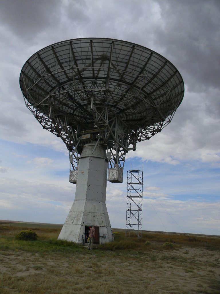
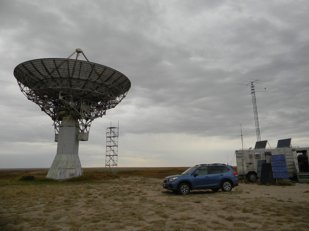
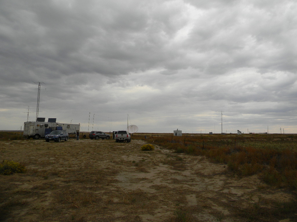
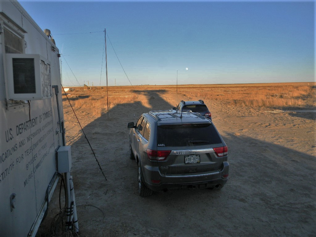
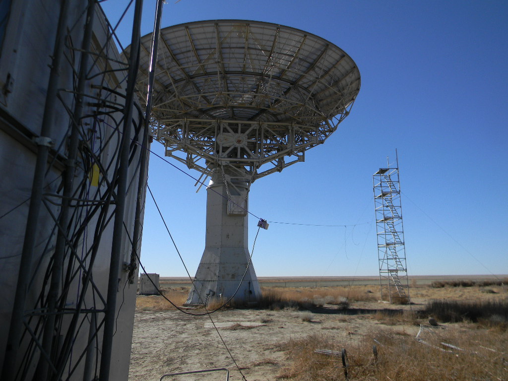
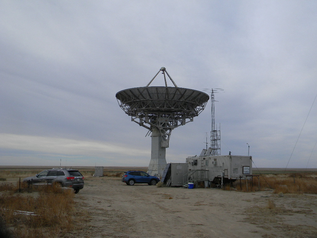
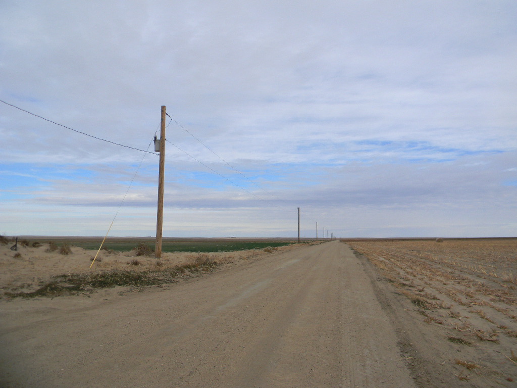
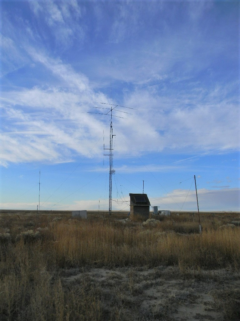
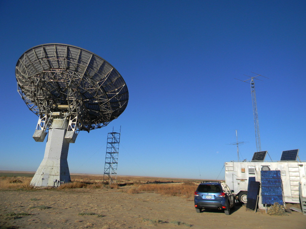
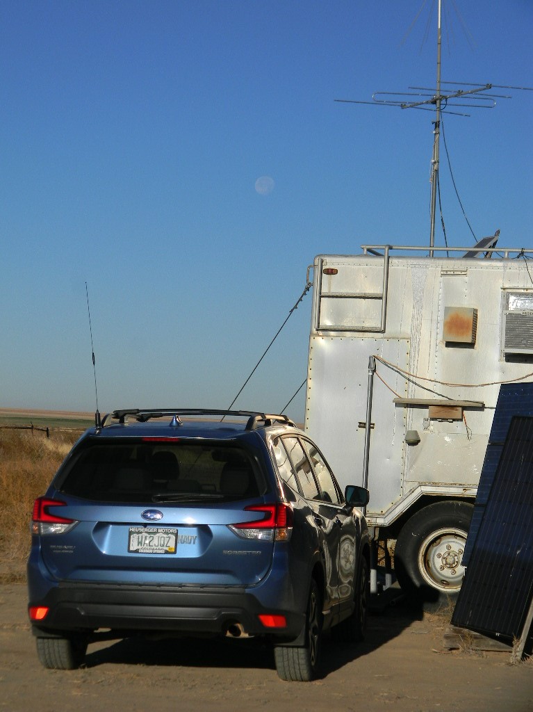
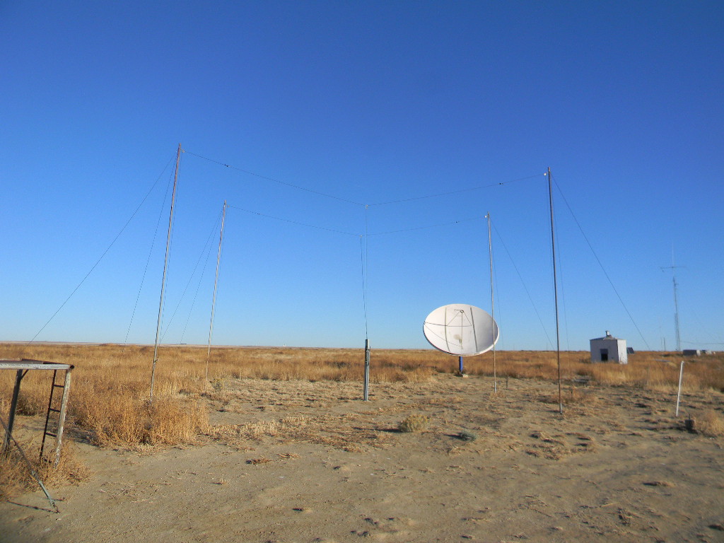
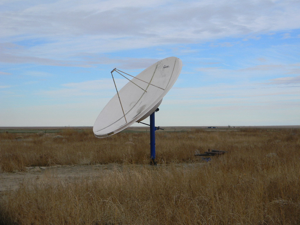
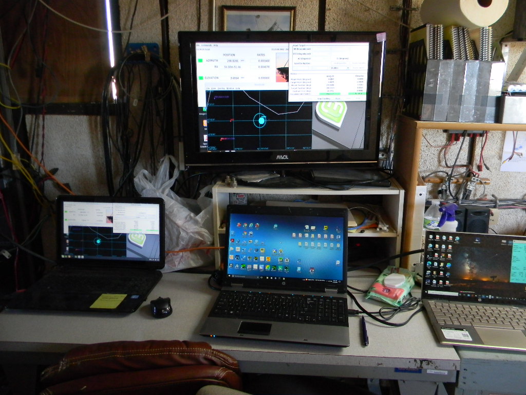
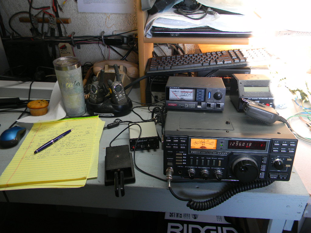
Our 60-foot dish antenna in stowed position and the operations trailer, during the daytime break Saturday, before the Moon rose again after sunset. The antenna focus has installed a 1296 MHz dual polarized feed.The power lines on Delores Lane that provide our site with electricity. Our high frequency (HF) ham radio antennas on the site. On Saturday afternoon while we waited for the Moon to rise again, I operated for a couple of hours for an ARRL HF contest: the November SSB Sweepstakes. I used the directional Yagi antenna on the tower and a multi-band vertical antenna at left. For the Sweepstakes contest I made 57 contacts around the continental US and Canada, plus with Hawaii and Puerto Rico. Before that I also made some casual contacts, mostly with hams who set up at parks in various parts of the country.After about 1 AM each night we took a break and got some sleep. When we woke a few hours later, the Moon was still above the horizon and we operated Moon bounce for a little while longer. On Saturday morning that gave us contacts with DU3T in the Philippines and VA7MM in British Columbia, Canada. This photo is on Sunday morning as we repointed the antenna to the Moon, near the horizon above my car. On Sunday morning we made no further contacts, but if anyone else was there on the air we would have heard them.The two wire antennas in the foreground are phased dipoles, which we use for receiving natural signals from Jupiter and its moon Io, caused by Io moving through Jupiter’s strong magnetic field. The 12-foot dish antenna is a new project that will be part of a radio astronomy interferometer we are developing.Closer view of one of our dishes we will use for radio astronomy interferometry.Our operating station early Sunday morning. We had coffee and muffins ready.You can see the antenna tracking software displays. The Moon is shown on an astronomical sky map. The circle around the Moon represents the beam width of our signal. Other windows on the display indicate the coordinates the antenna is pointing to, its motion, and settings for how we are controlling it. On my laptop on the far right, I have a logging program (not shown) and a program that shows me the position of the Moon (in Az & El and RA & Declination), and the Doppler shift corrections we need to continually make as our relative motion between our location and the Moon changes.The ICOM transceiver we were using, tuned to 1296 MHz, and the Morse Code keyer for sending code. We had the keyer set for 15 words per minute. I wrote down (copied) the code that I heard on the paper pad. I save the hard-copy record, in case I need to double check a call sign or a contact detail for the contest or QSL request.The farm and ranch fields across the road from our site.
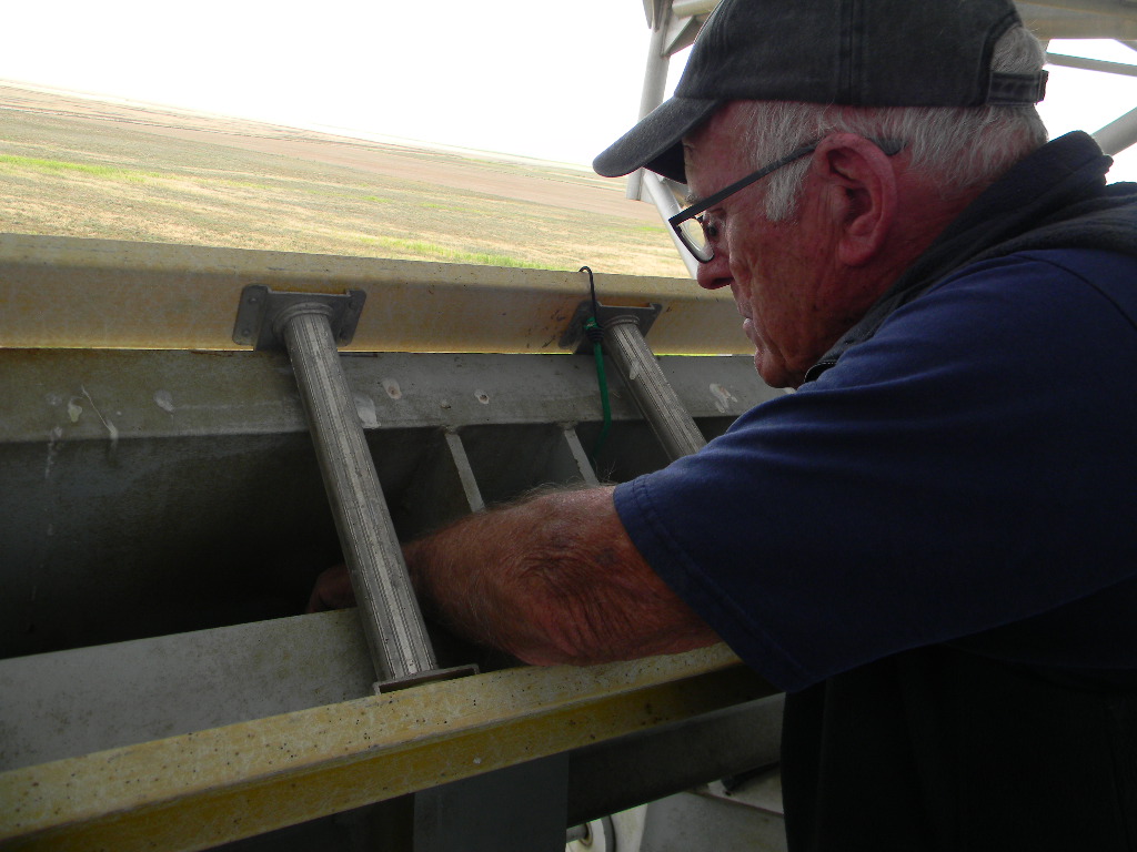
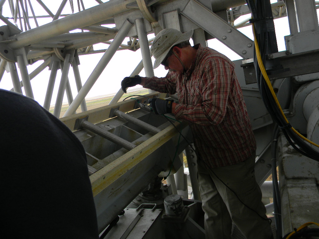
Lewis Putnam and Glenn Davis worked at the Plishner antenna site on Monday November 1. Lewis wrote this trip report to describe what they accomplished. The major reason for the work trip was to evaluate the mount pointing errors after the replacement of 1420 feed.