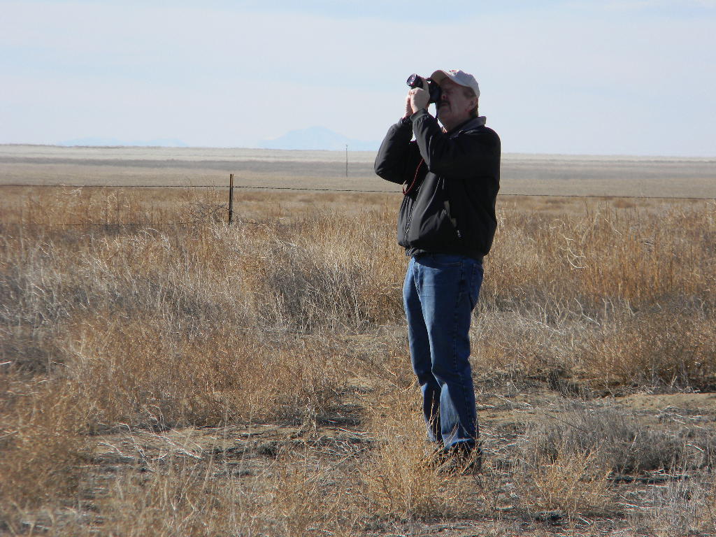
Text & pictures by Bill Miller.
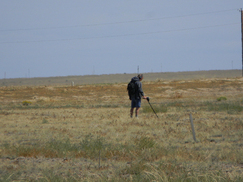
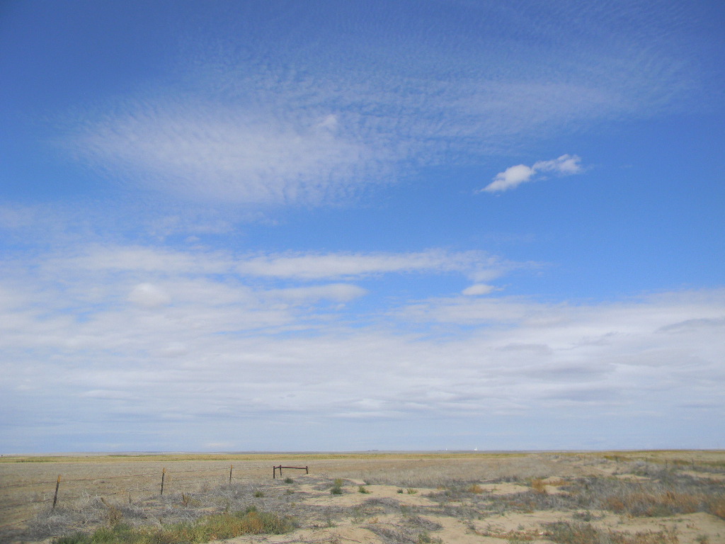
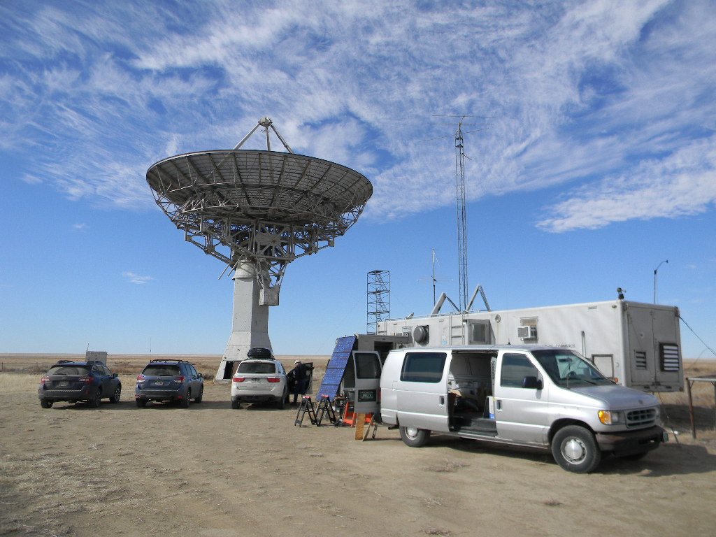
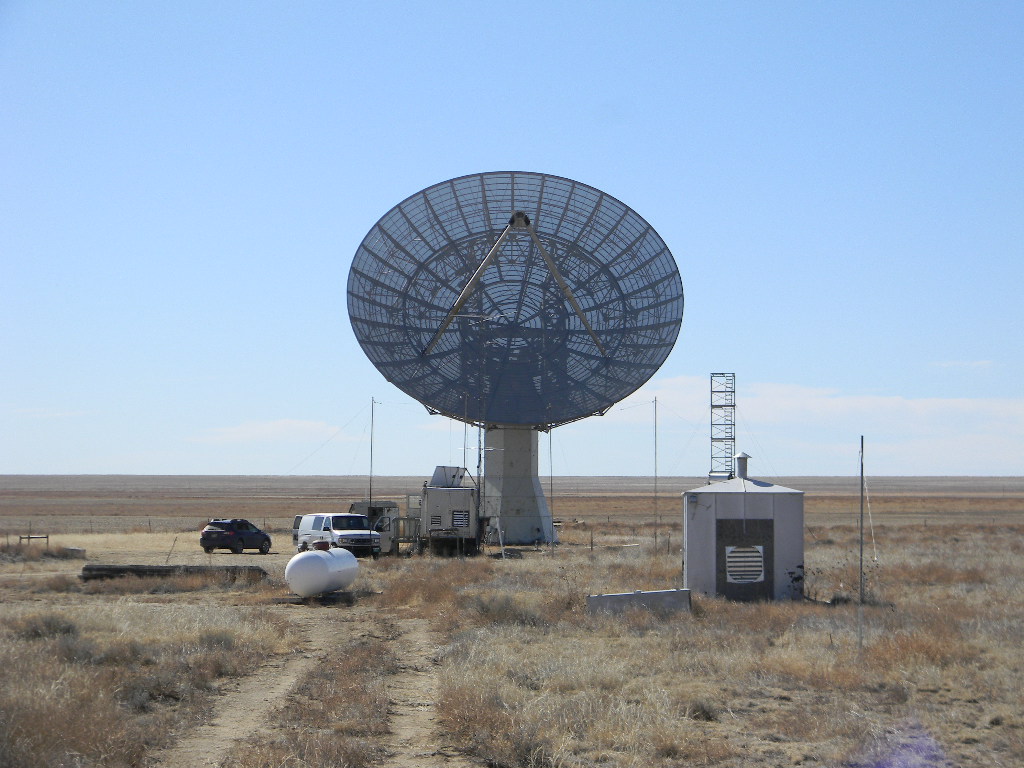
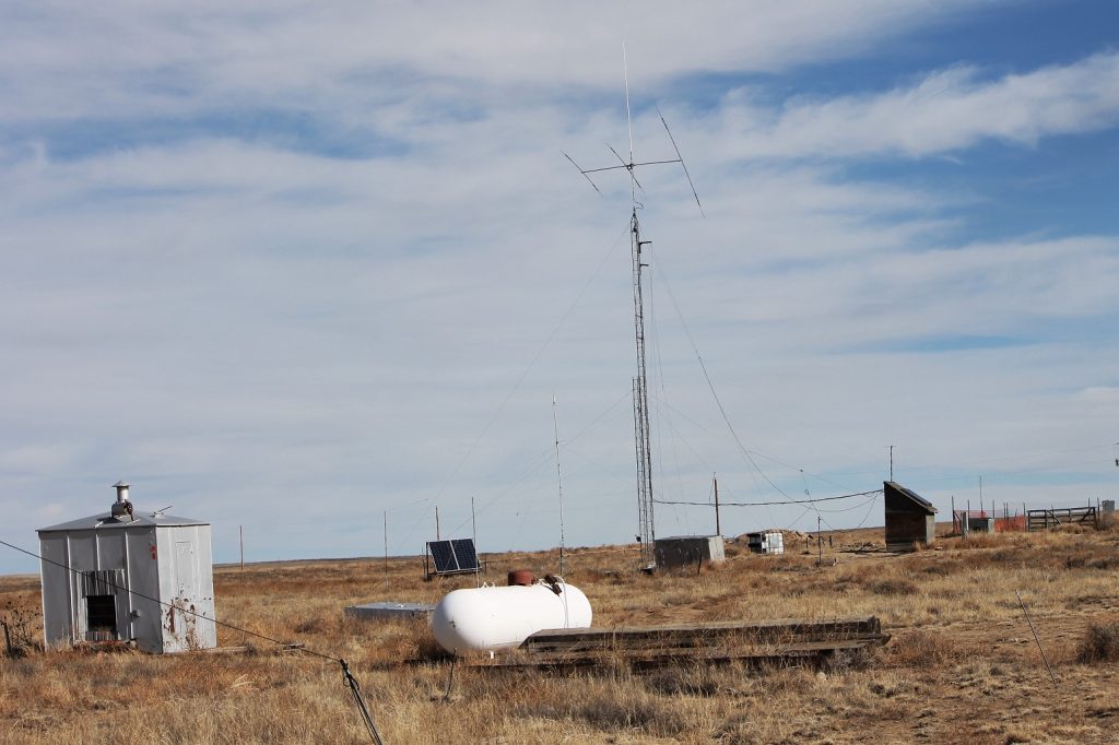
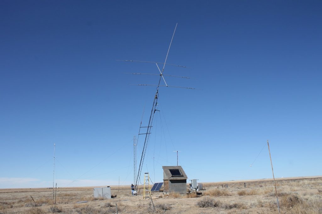
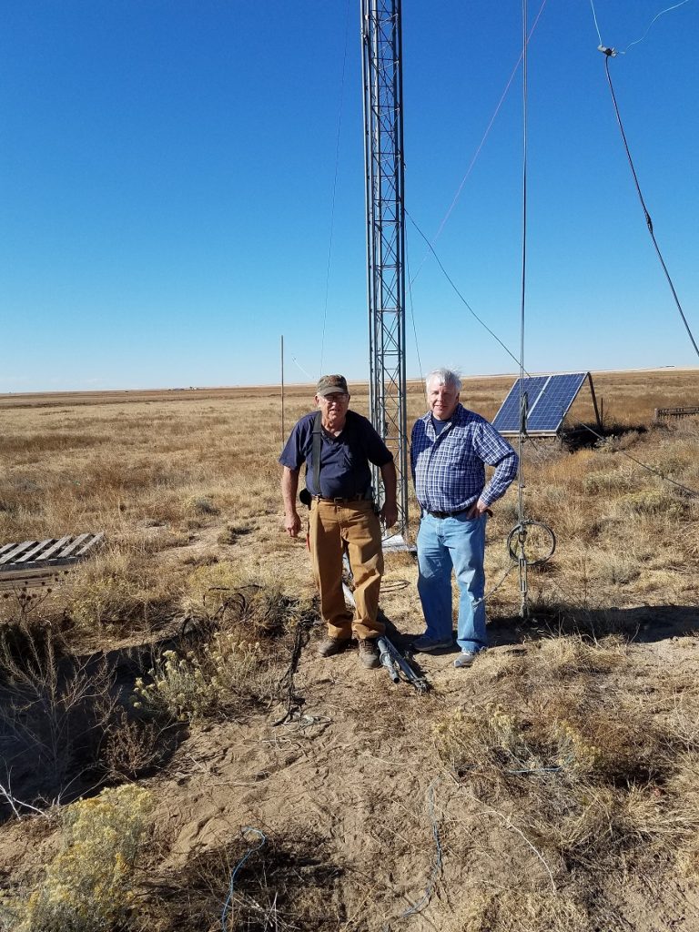
On Tuesday 12/08 Ray Uberecken and Bill Miller traveled to the Plishner site. We found that the gate chain lock was not properly attached to the post and could be removed without unlocking it
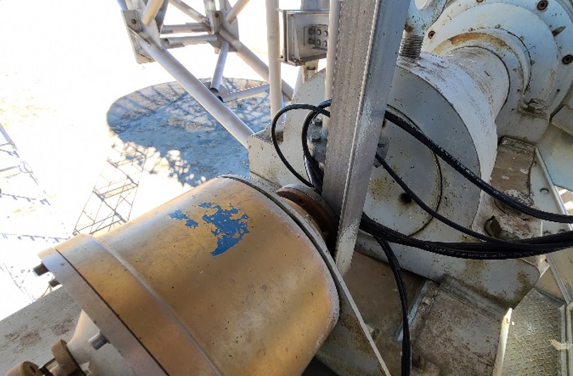
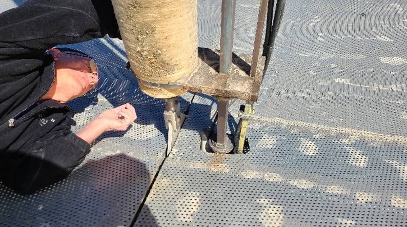
We replaced two of the coaxial cables running from the dish pedestal control deck to the upper deck just below the dish. These cables had stretched from their own weight and from the elevation rotation of the dish. As a consequence the center pin pulled out from the mating connector, losing the conductivity. We added to the cable a loop over the elevation axis. Ray added a feedthrough connector attachment on the ceramic slip ring collar, in order to remove the rest of the hanging stress on the wires, and he re-added the swivel joints below that. This arrangement completely eliminates the cables traveling up and down thru the collar as the elevation is changed, and this also virtually eliminates the coaxial cable wrap in the control deck area. We redressed all of the cables there with tie wraps and tape to get them out of the way of personnel in the deck and to remove the mechanical strain on all the cables.
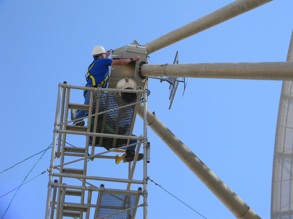
At the top deck we removed the AC extension cord, which had been temporarily installed to a power amplifier at the feed for EME. Its cord insulation might not have survived the winter, and the uninsulated cord could potentially short out to the structure. A more permanent and reliable 120 volt power distribution is needed to the feed point.
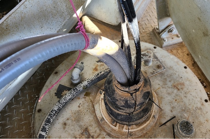
We also re-dressed all the wires and coax cable in the upper deck. We reused the pipe grommets as a weather shield for the cables going down thru the azimuth axes collar to the control deck level.
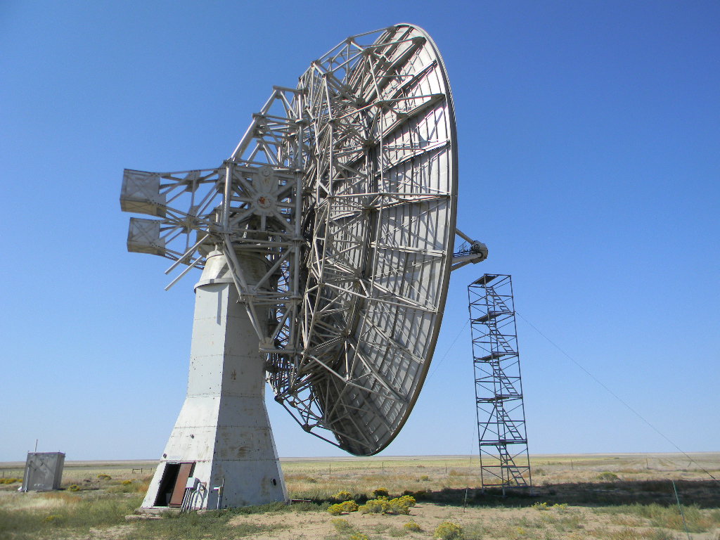
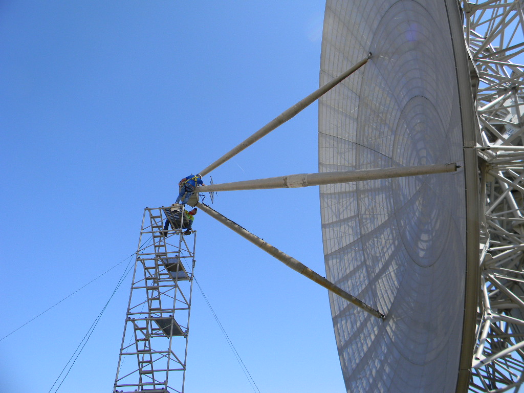
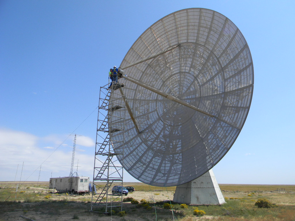
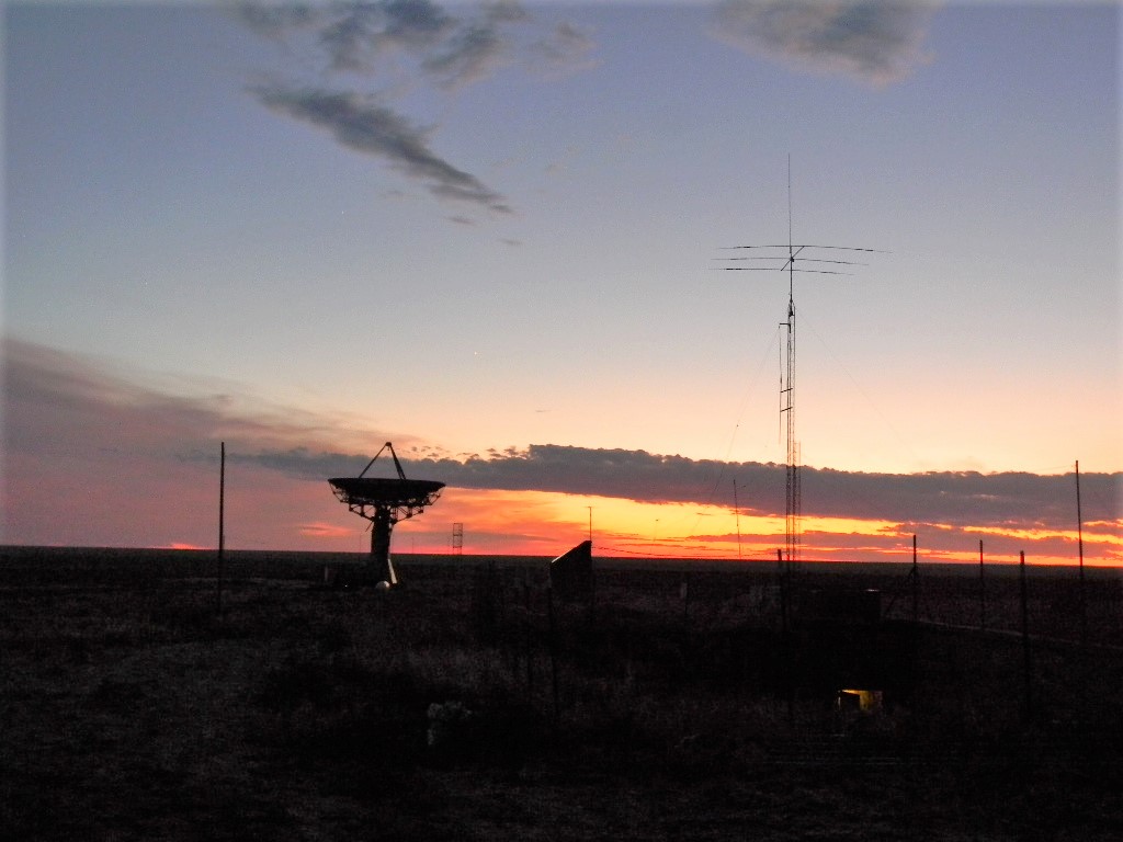
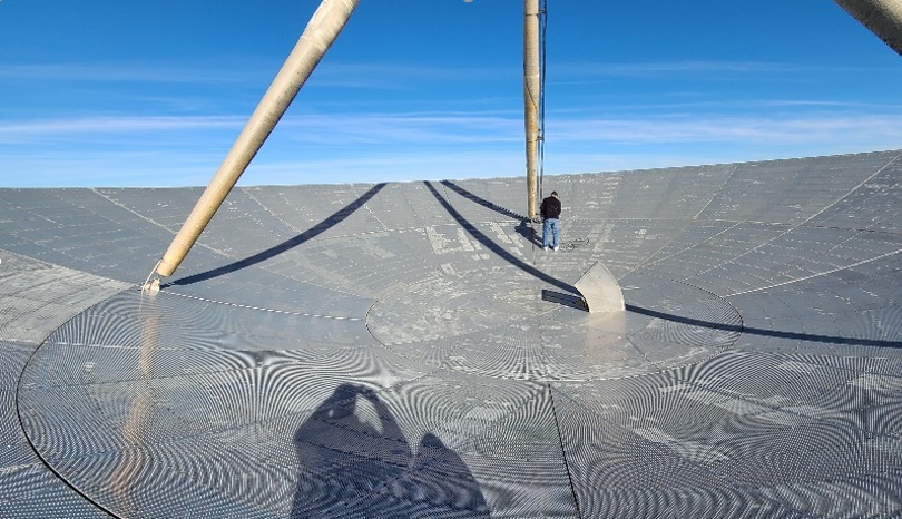
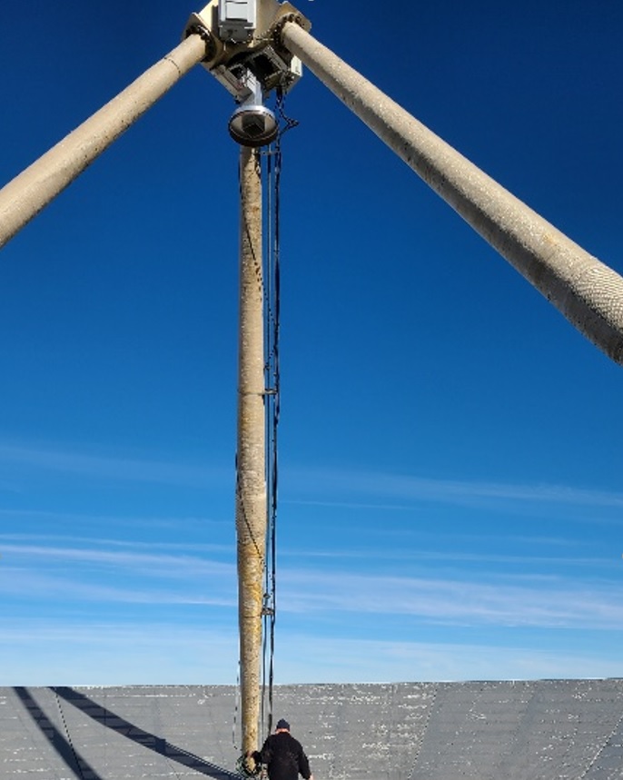
We then placed a ladder on the mount and proceeded up to the dish surface. There we continued to remove the 120 volt extension cord, and we inspected the surface and the support. This is a wide angle shot of the scene in the dish. It does give a sense of the surreal feeling of the view from there.
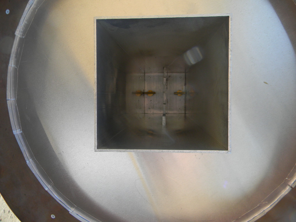
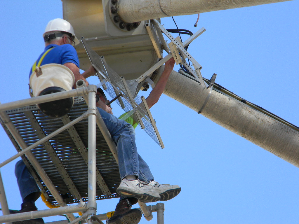
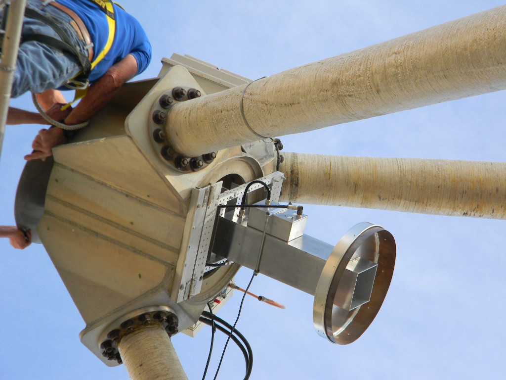
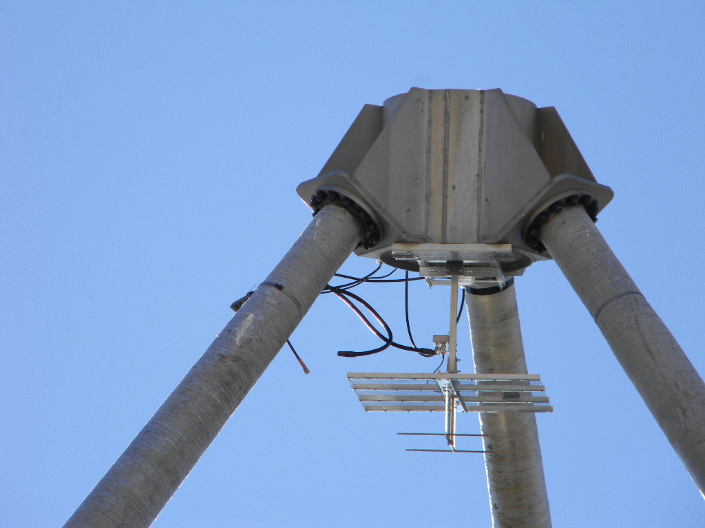
We inspected the attachments and connections. We discovered that the grounding cable connection on one of the legs leading to the focal box had been cut off. Furthermore, the wave guide that is attached at the dish structure is not electrically attached to the focal point box. Therefore the only ground to protect from RF, lightning, or static is the coax shield and the low voltage control cable ground wire. This may be one of the causes of failures in the electronics. We should retrofit to provide a good DC ground connection between the feed box at the focal point to the pedestal.
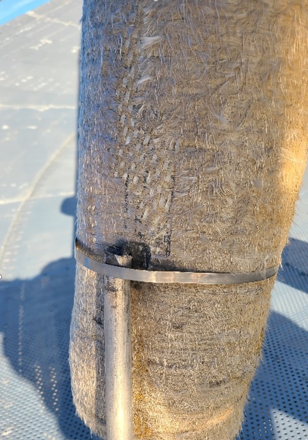
We also wanted to know how the fiber glass supports for the feed are adjusted.
The fiber glass supports are badly weathered after 60 years in the open. We should derive a plan to rework the fiberglass surface, for the next time we rent a bucket lift to work on them.
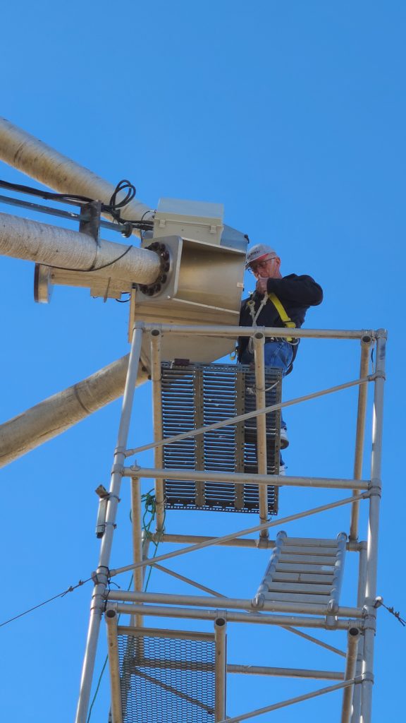
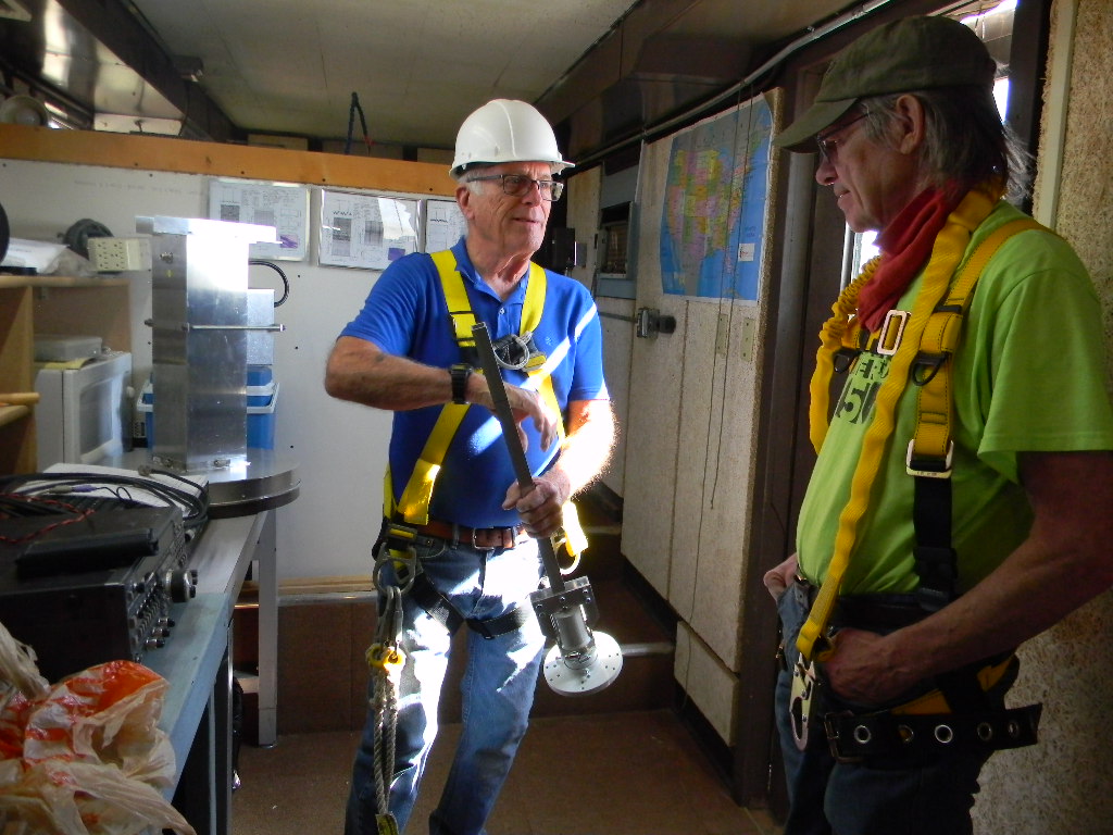
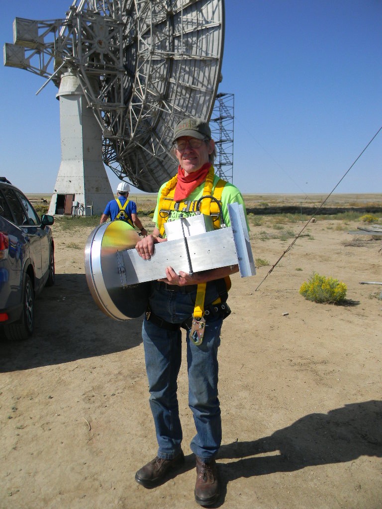
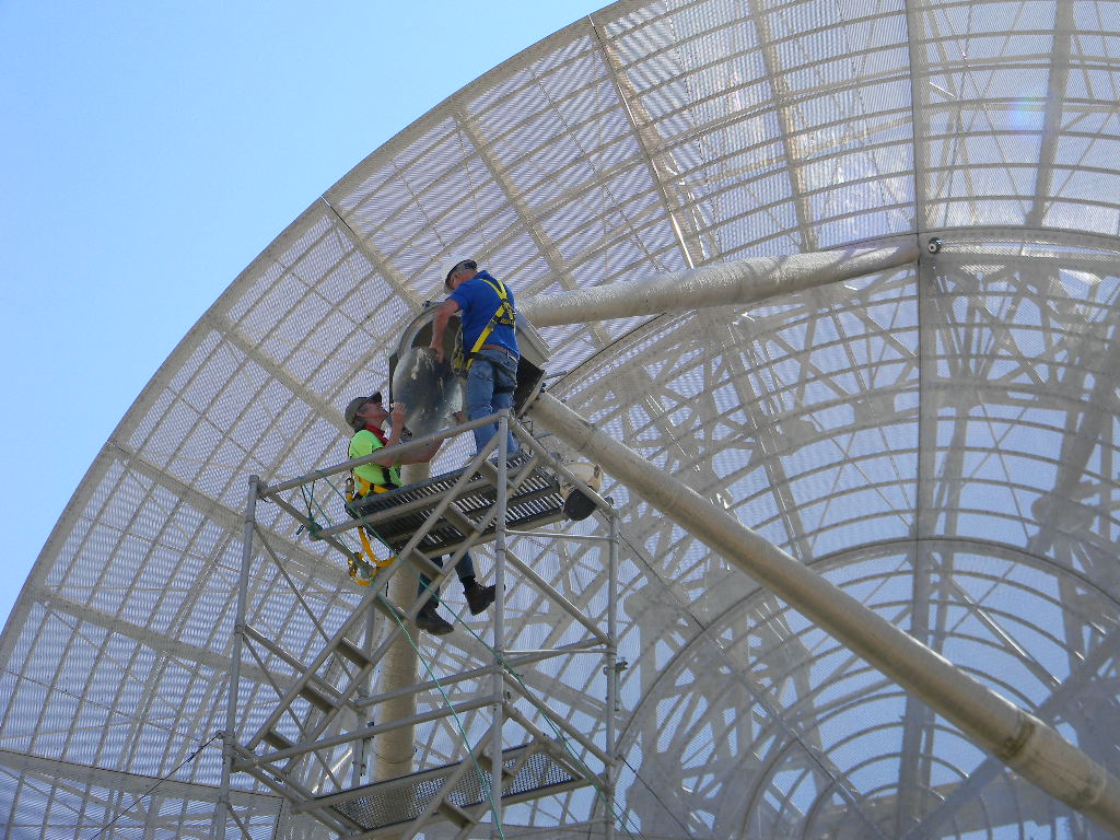
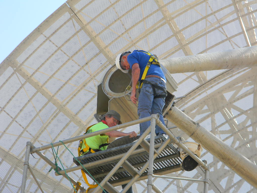
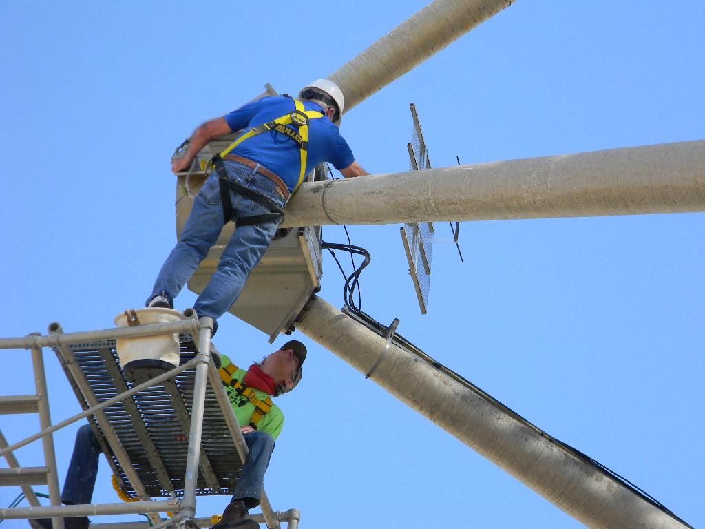
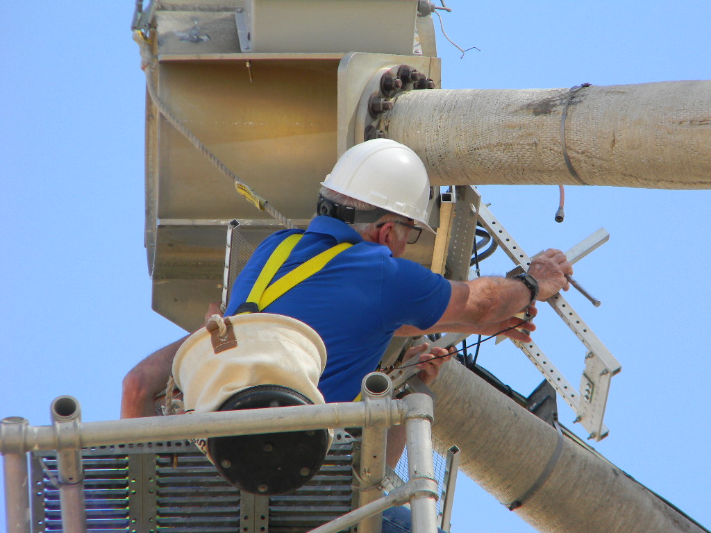
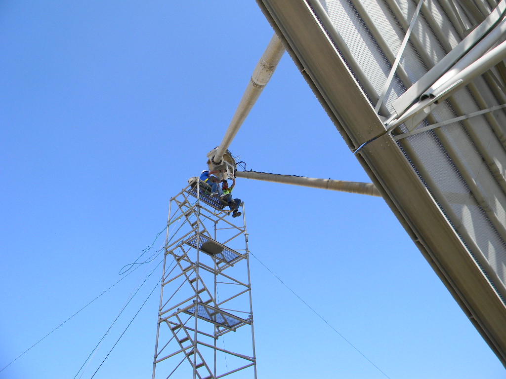
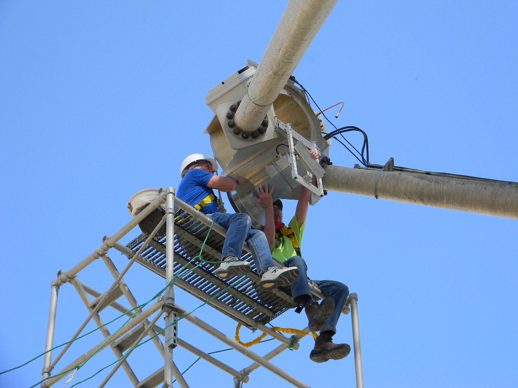
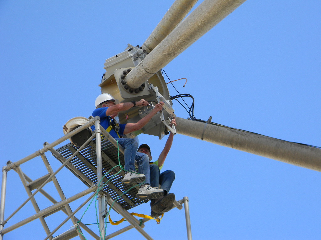
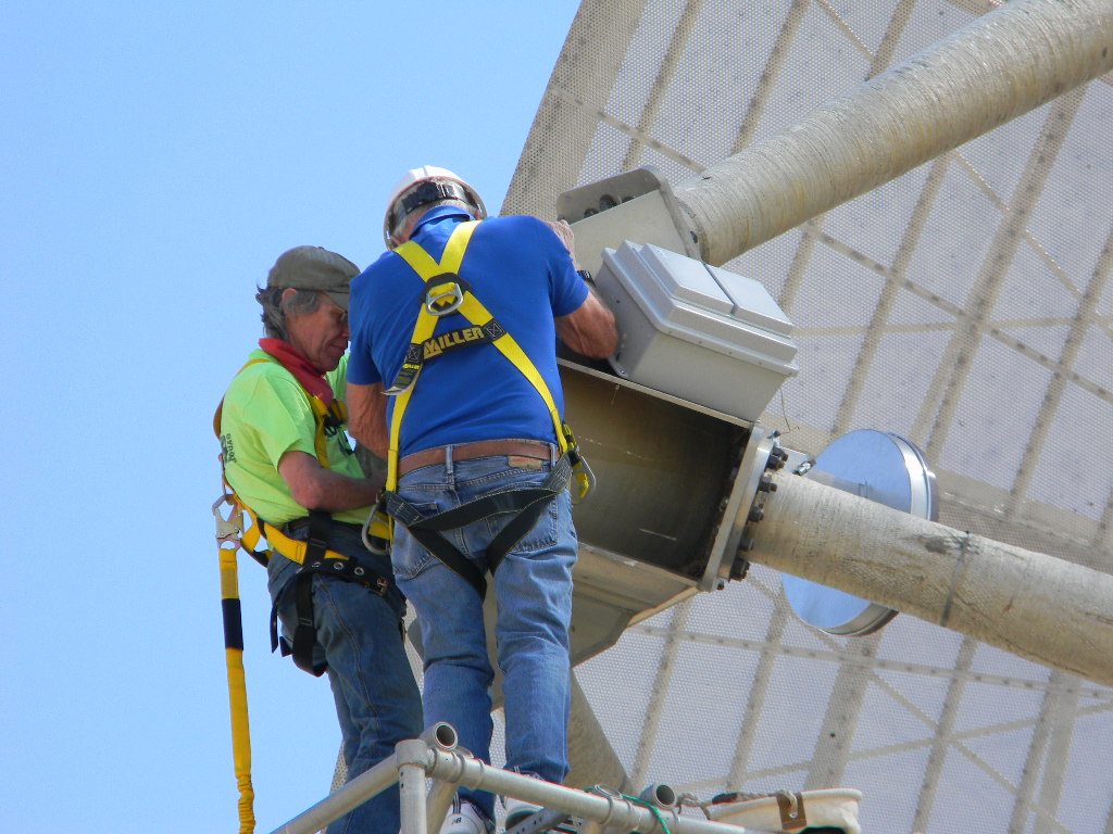
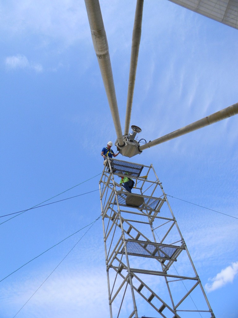
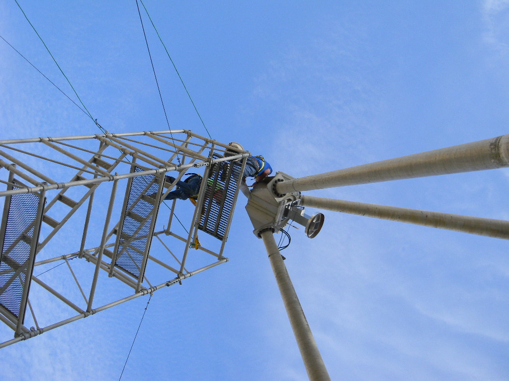
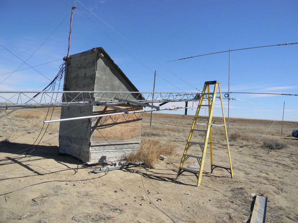
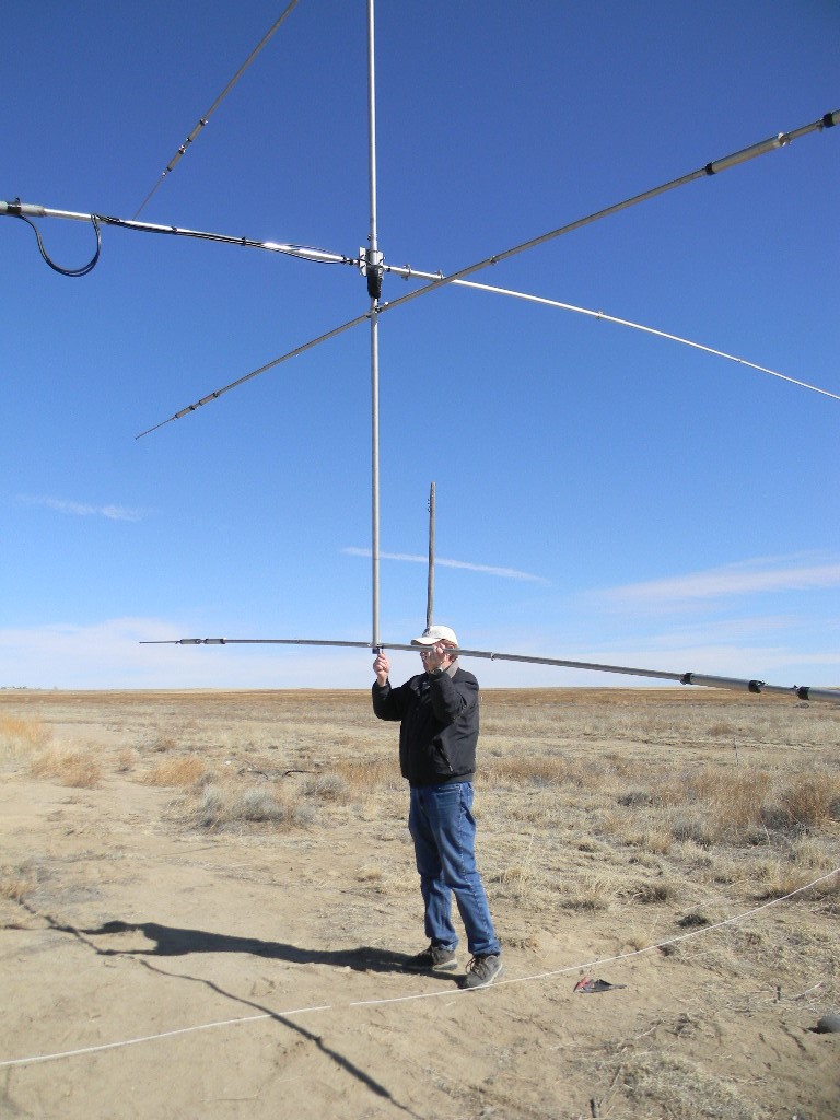
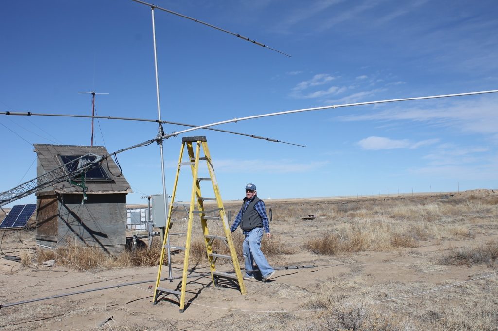
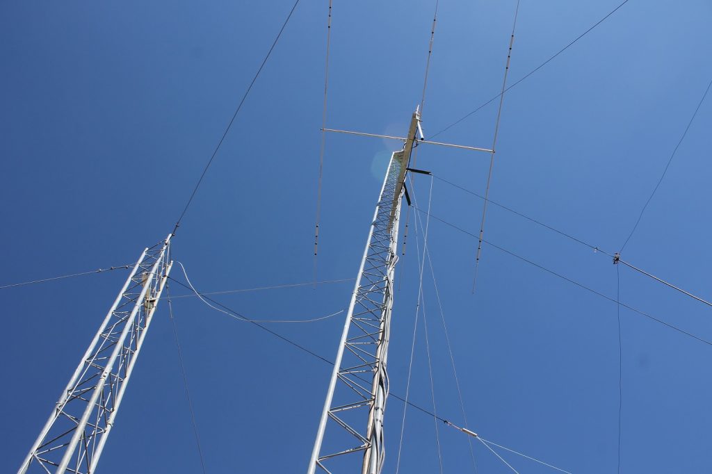
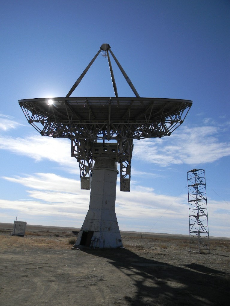
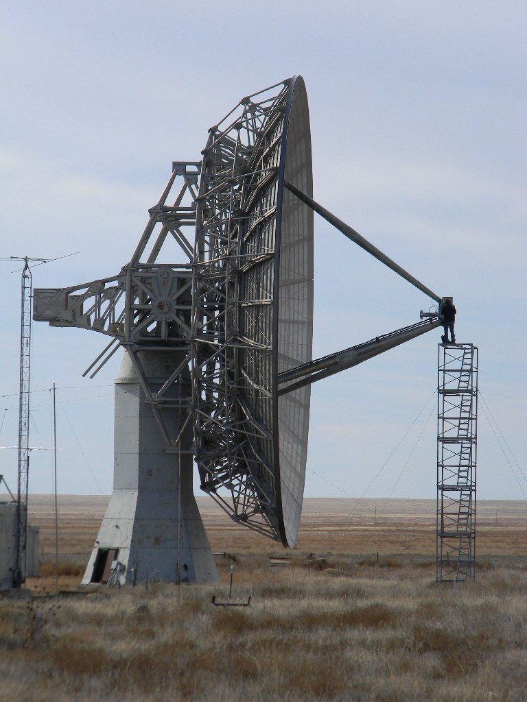
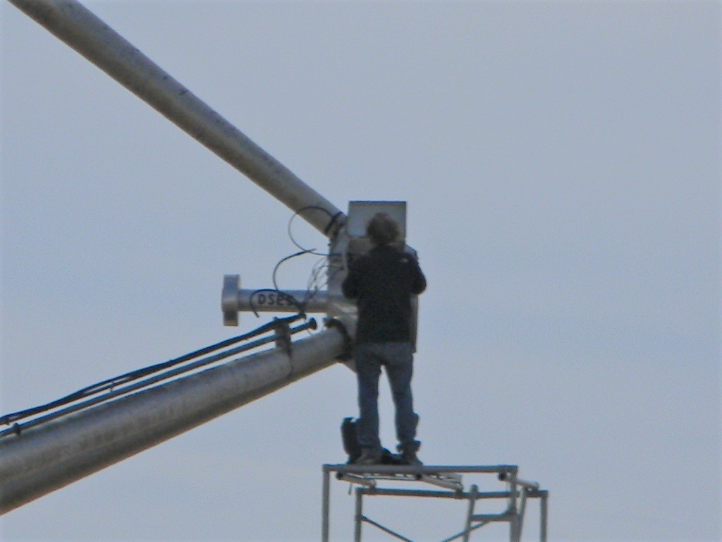
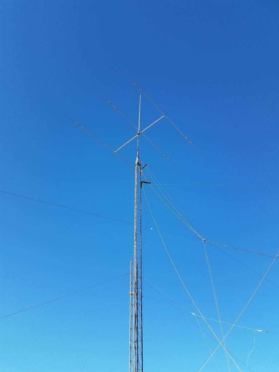
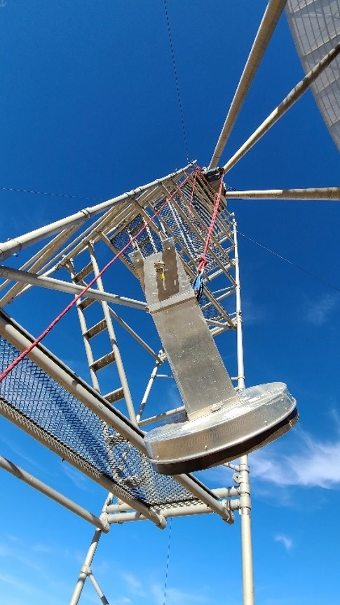
Once we had inspected the dish, we tipped the dish down to the service elevation, donned climbing harnesses, and climbed the scaffold tower. We removed the 1296 MHz feed and installed the 408MHz antenna using Ray’s quick-change mount. This only took about an hour where before the process could take as much as half a day.
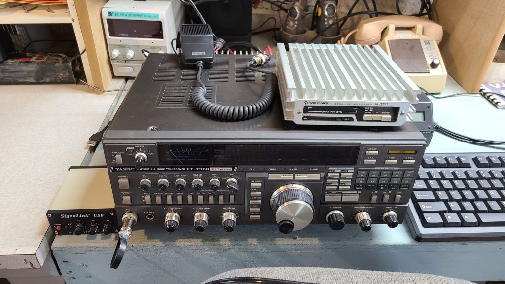
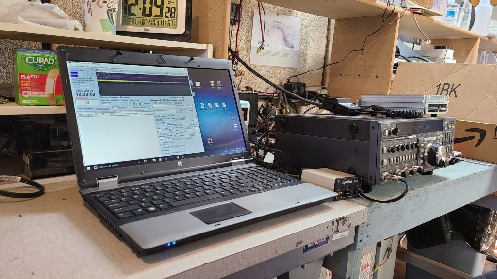
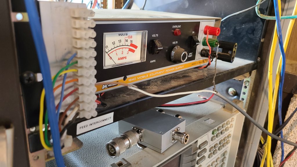
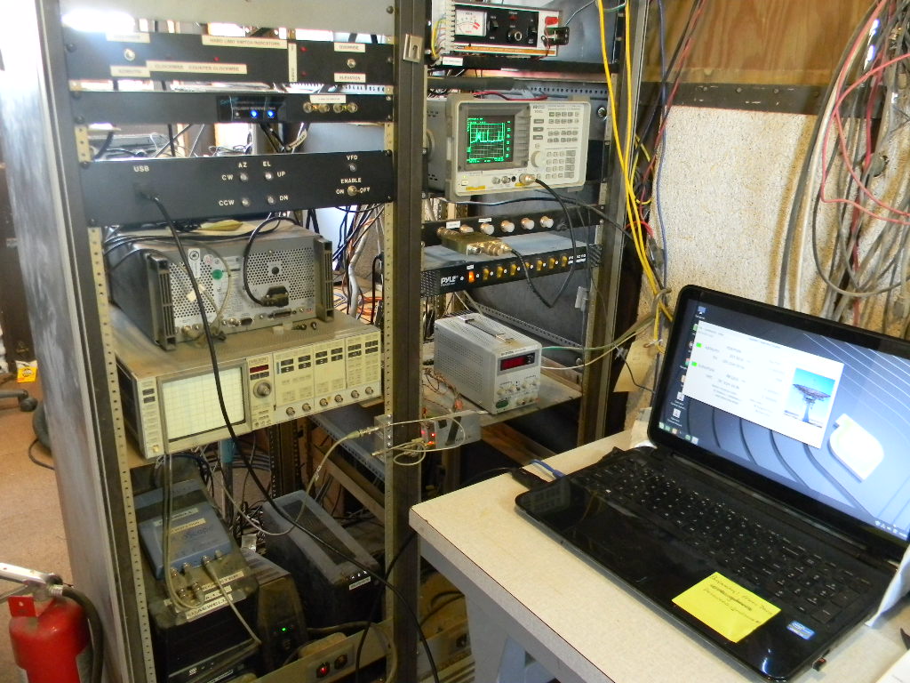
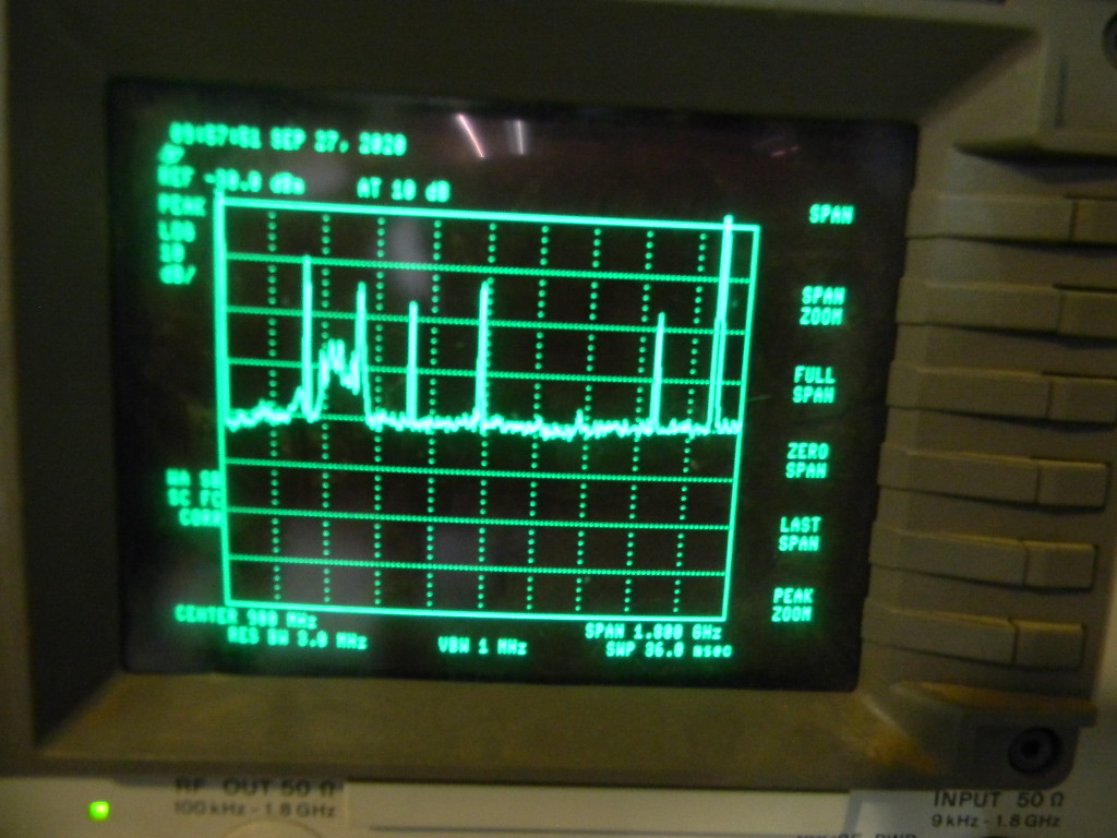
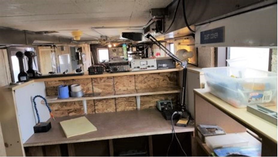
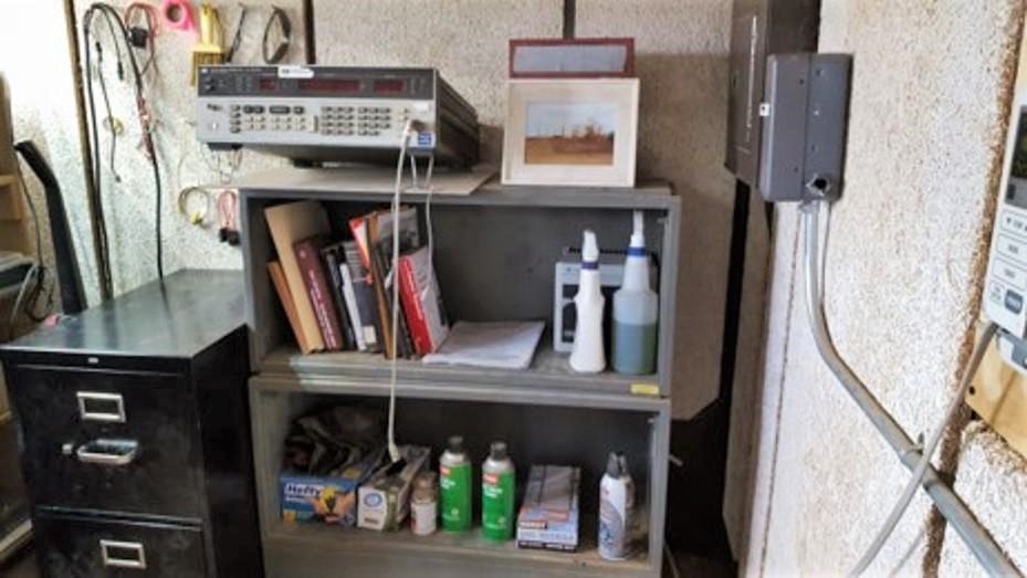
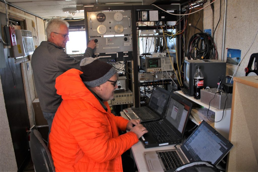
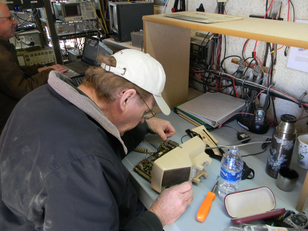
We also reworked the connector attachments in the electronics box. Ray then reattached the additional 20db amplifier, and checked everything out with the TDR and Spectrum analyzer. He reattached the cables in the pedestal to connect the correct coax lines to the Comm. Trailer.
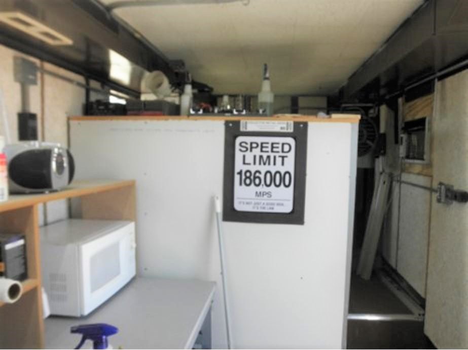
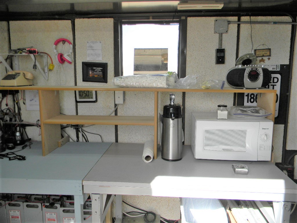
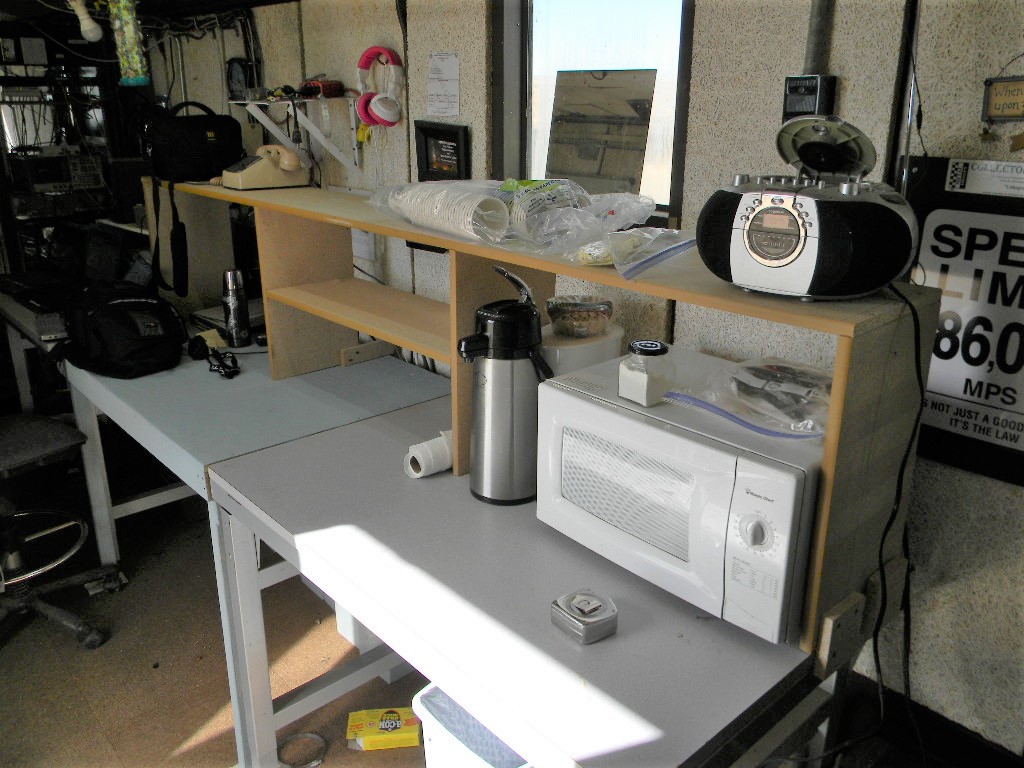
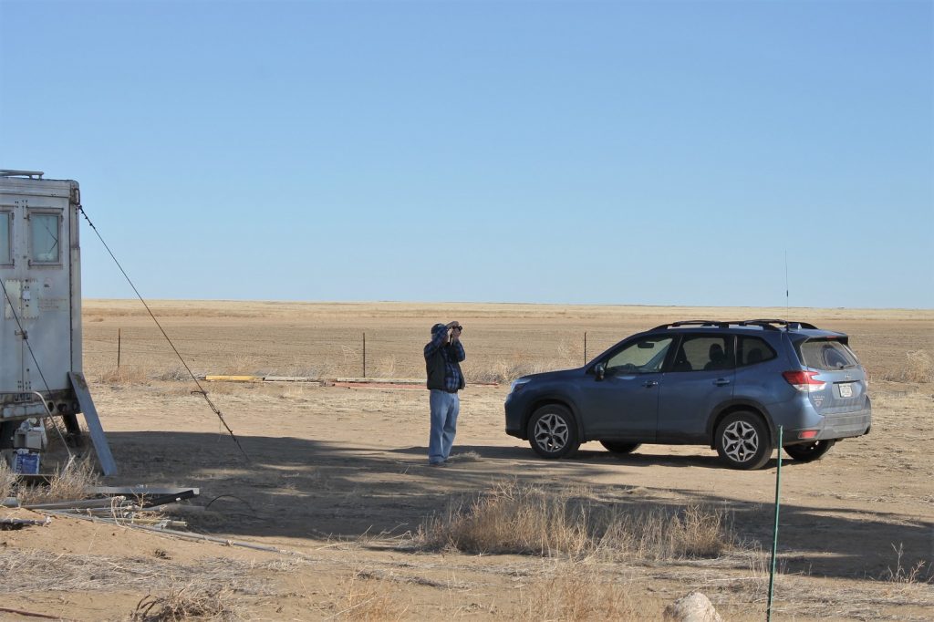
Bill replaced the broken window in the back of the comm. trailer with the new one he purchased from Kent Glass and sealed it with RTV. This provides a much clearer view of the dish from the trailer.
We parked the dish, turned off all the equipment, locked the site and left for the day.