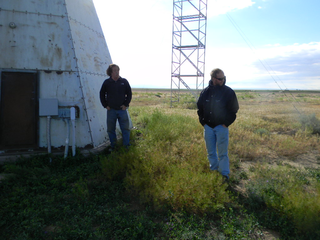
Participants: Steve Plock, Ed Corn, Rich Russel, Dave Molter, Gary Agranat.
Summary and photos by Gary Agranat.
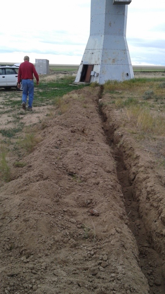
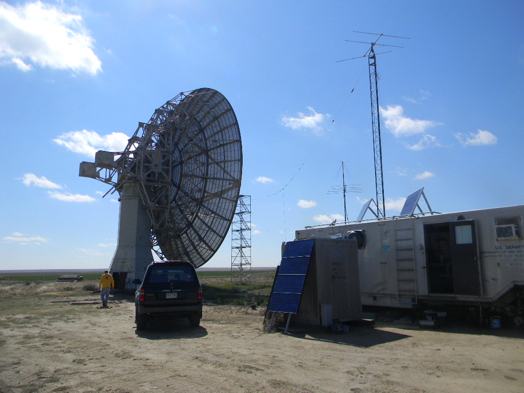
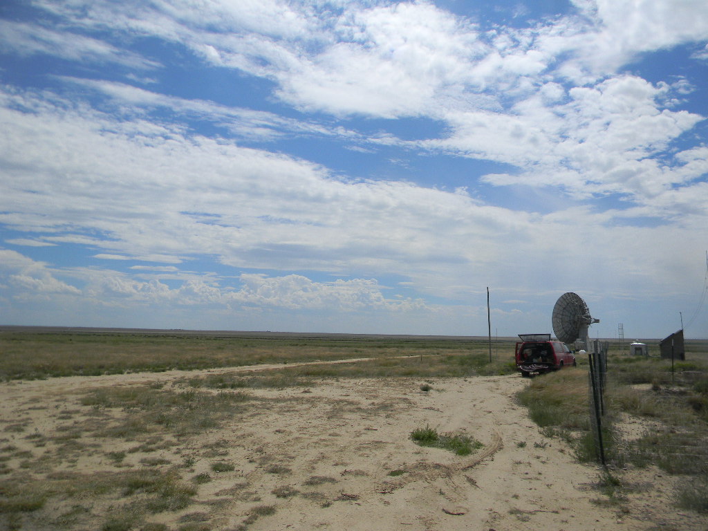
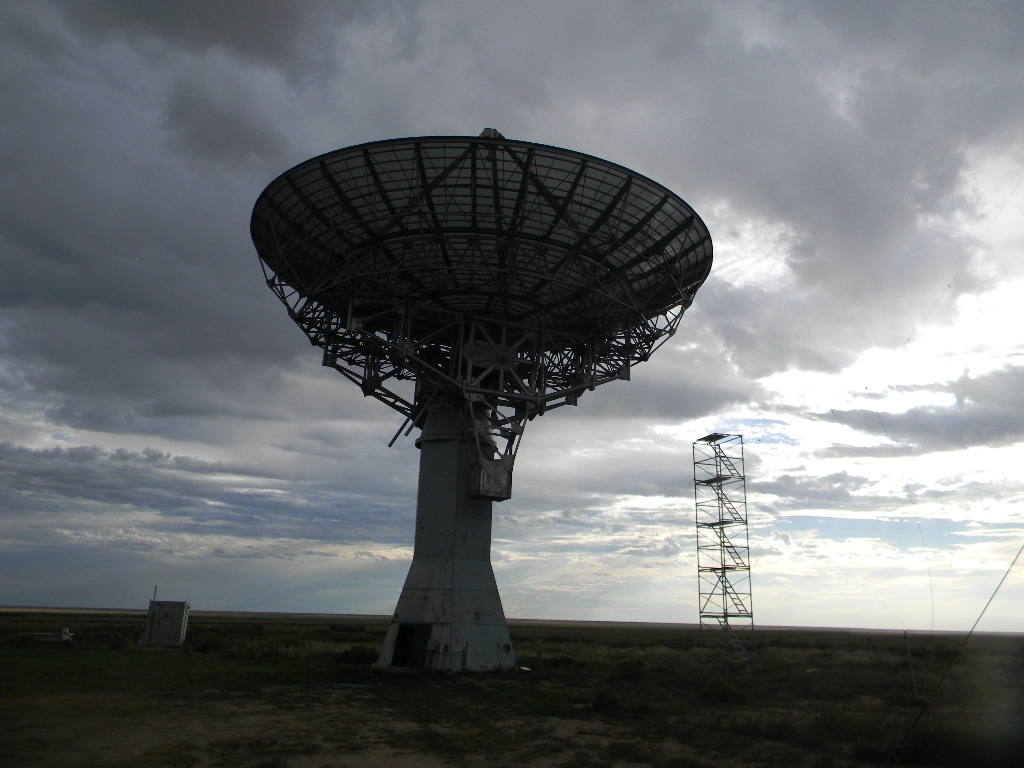
We worked at the Plishner Radio Telescope site on Saturday August 25, 2018. One motivation was to proceed with needed infrastructure work before the cold of winter returns. Another motivation was to follow up on the observations we made during the Open House with the 60-foot antenna. In addition, the antenna tuner for the bunker ham radio station was still not running, and needed to be checked. Here is a summary of what we did, with some photos.
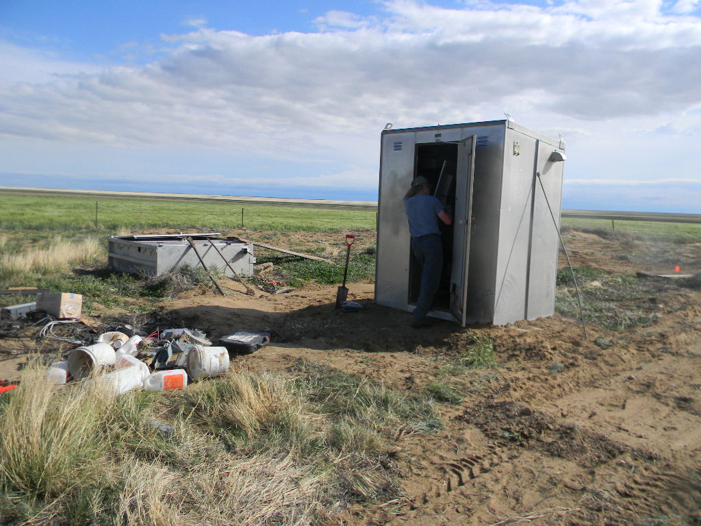
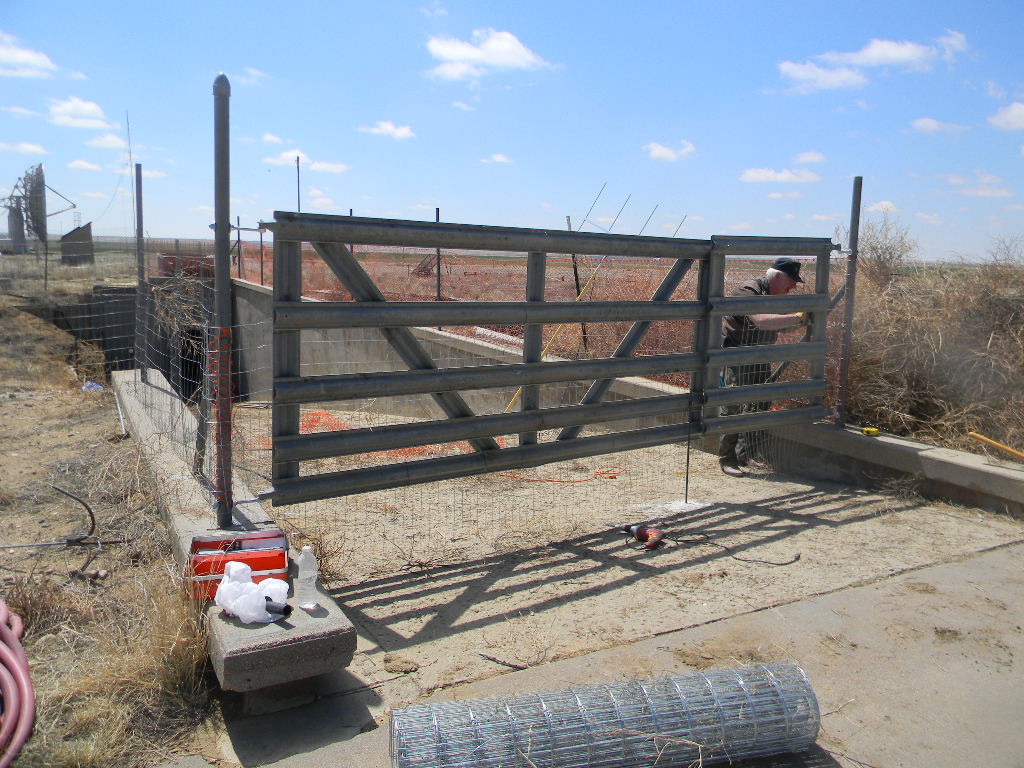
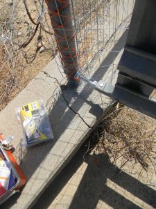
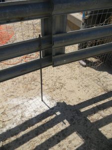
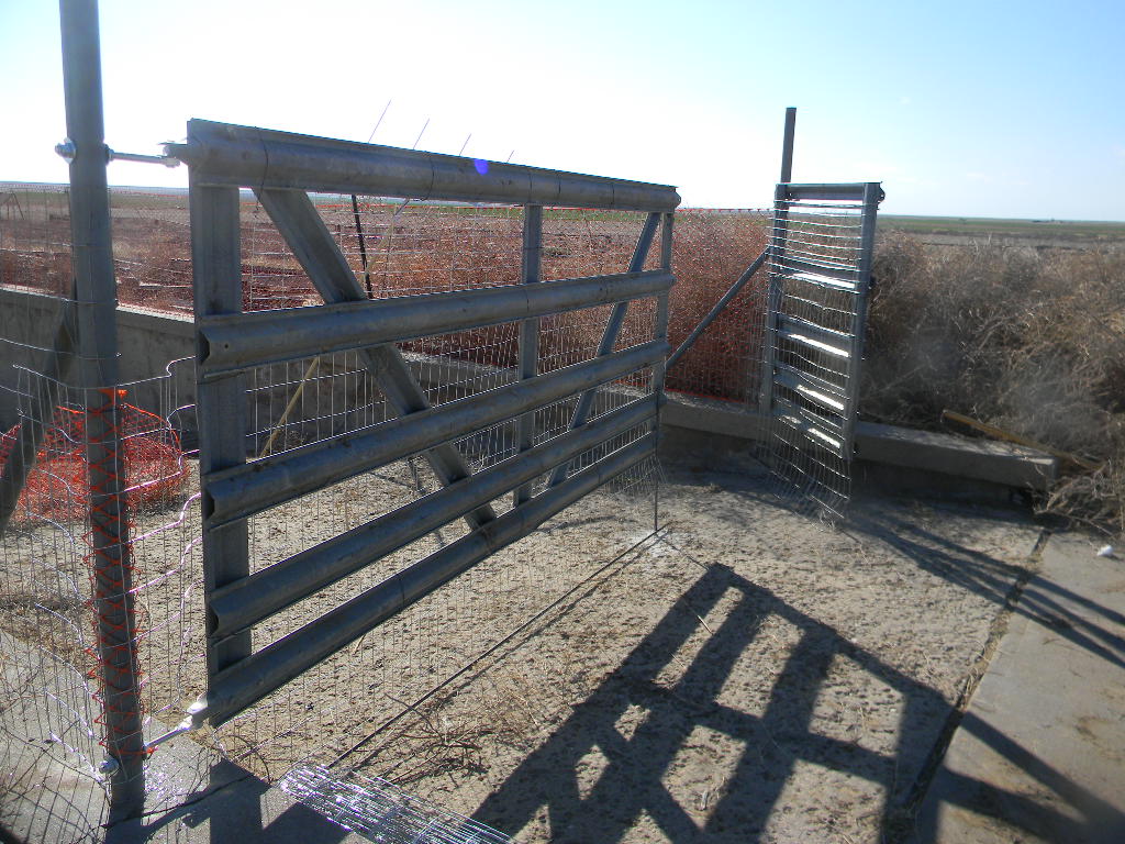
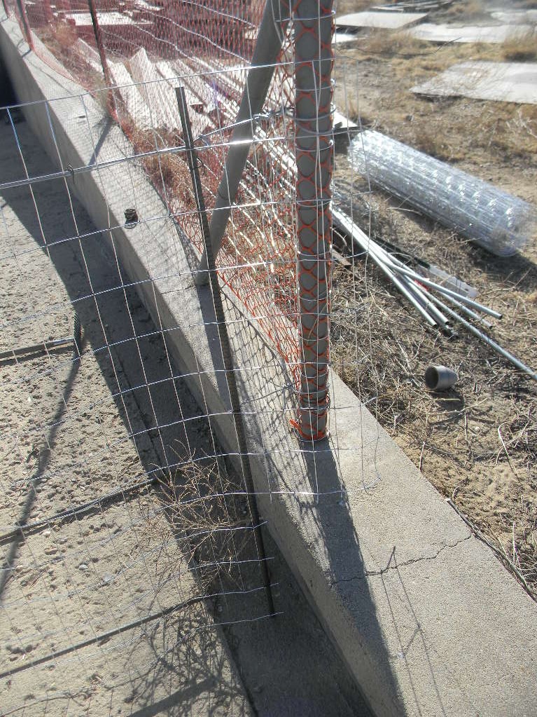
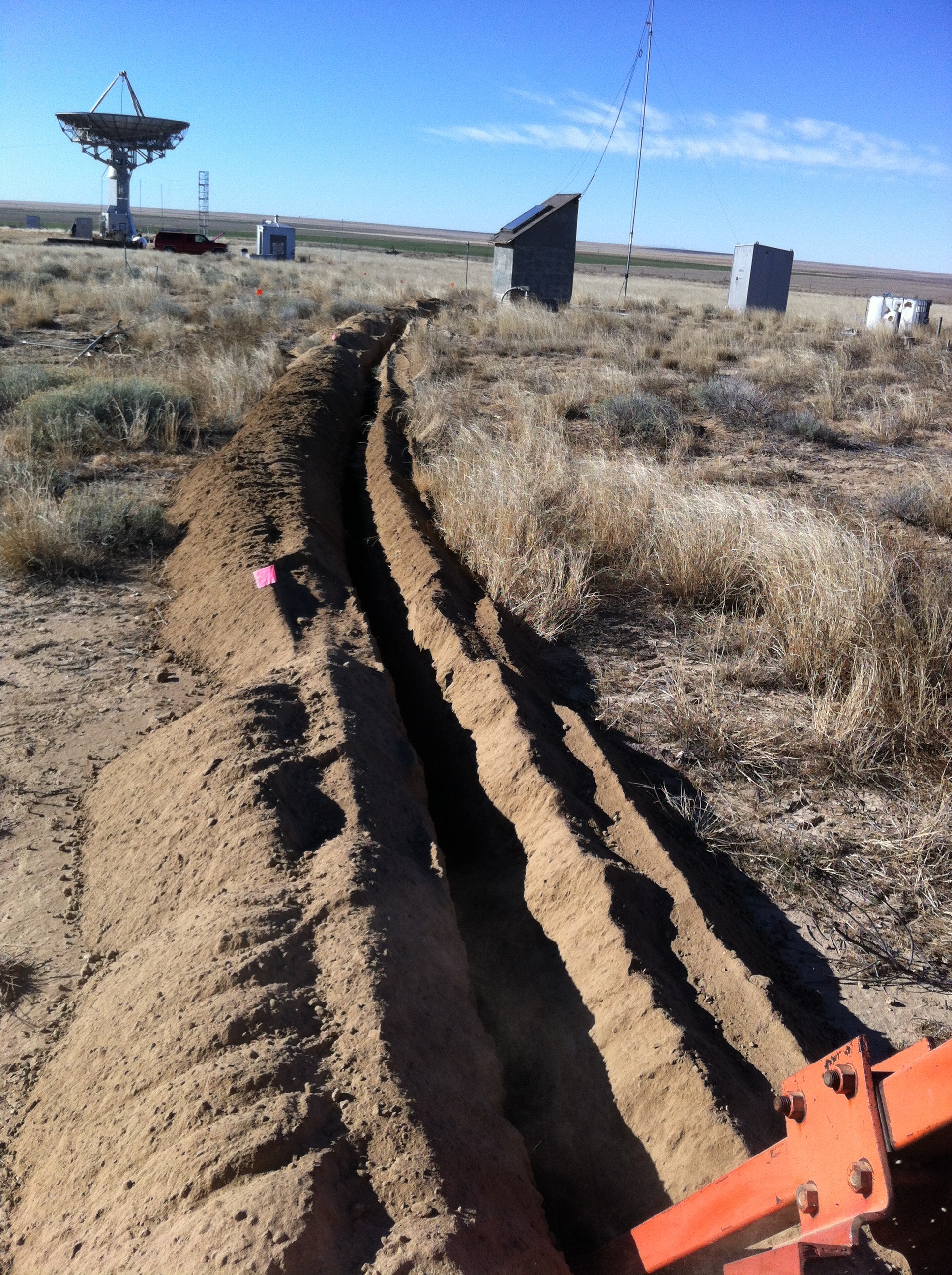
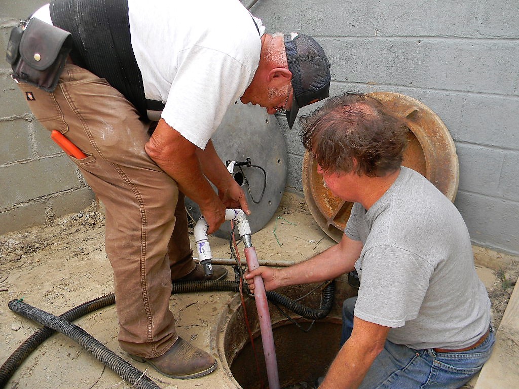
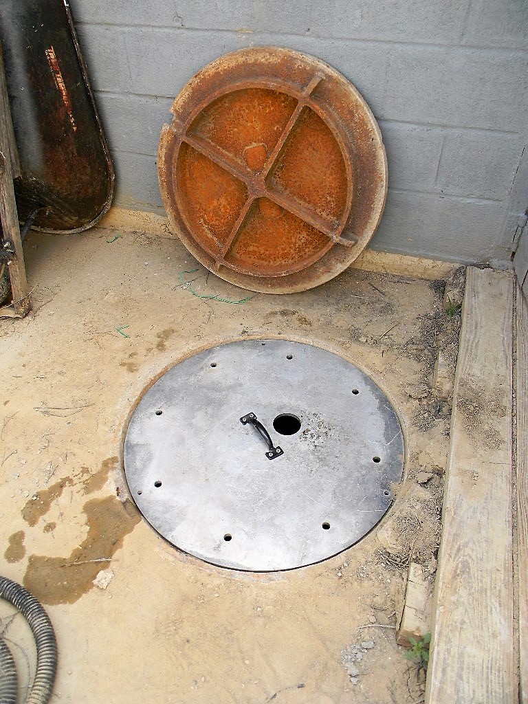
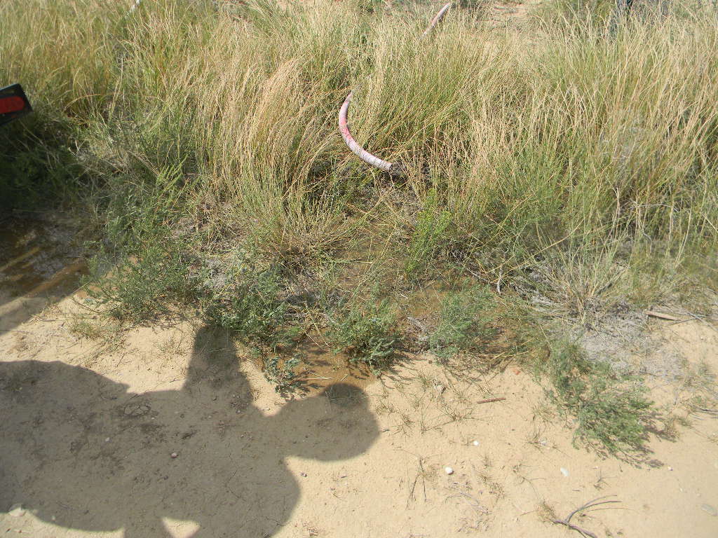
1. Ed and Steve replaced the outflow hose from the ramp sump with one more durable (including durable against mice). Ed tested that the outflow did drain away from the ramp area. We placed a new aluminum manhole cover on the sump access (vs the original steel one), fabricated by Steve.
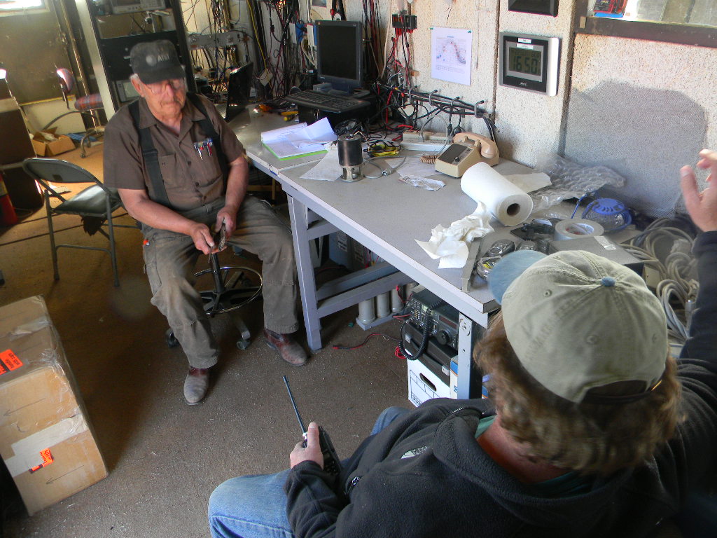
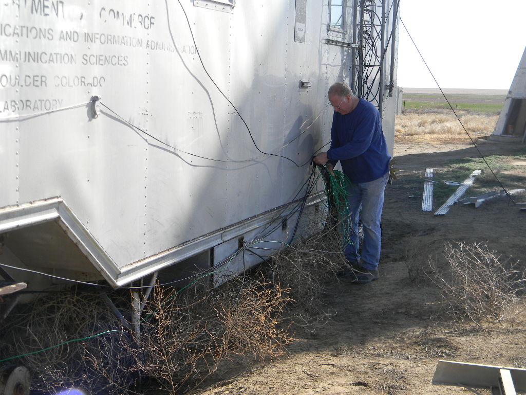
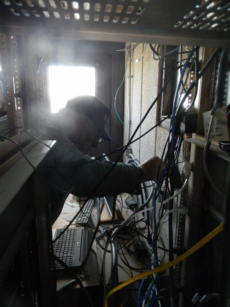
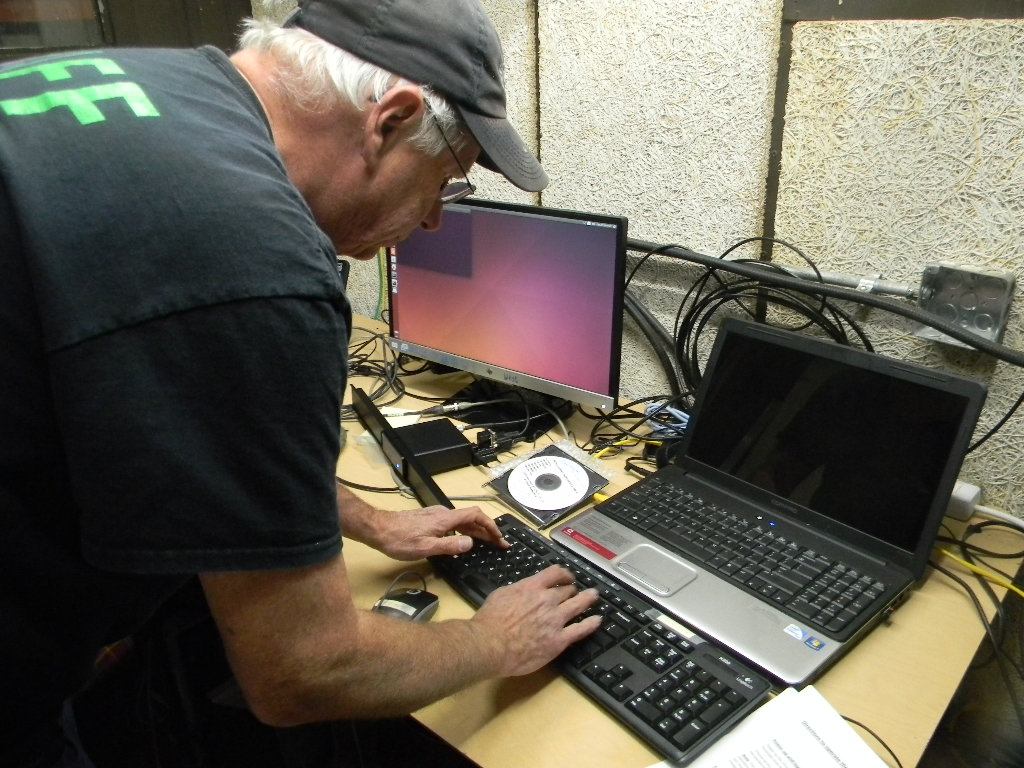
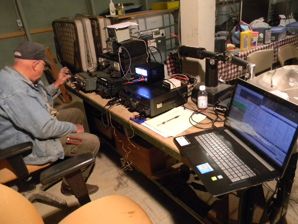
2. Ed moved the Internet hotspot to the bunker. The hotspot was used by Gary while testing and operating the ham radio station.
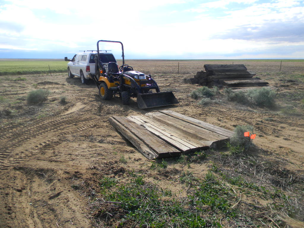
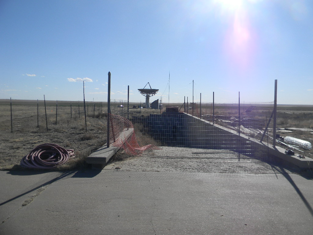
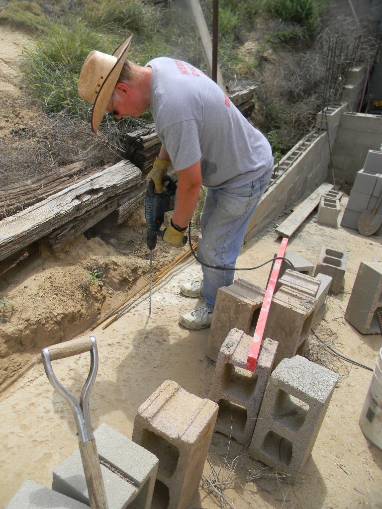
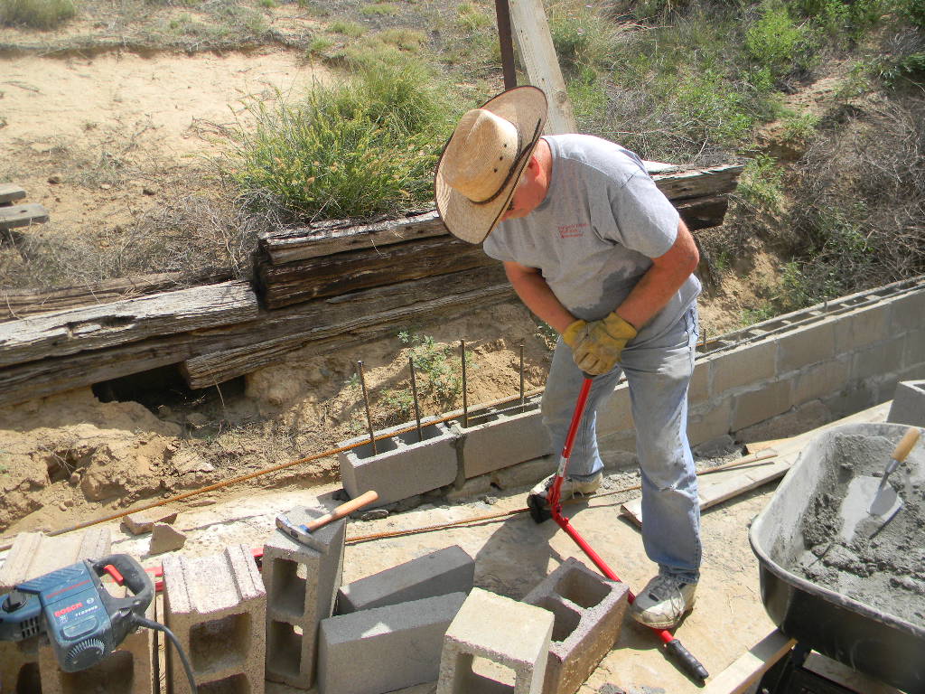
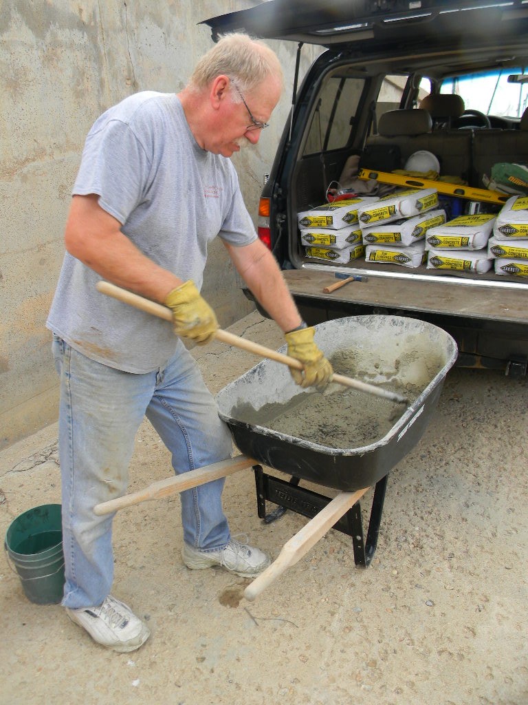
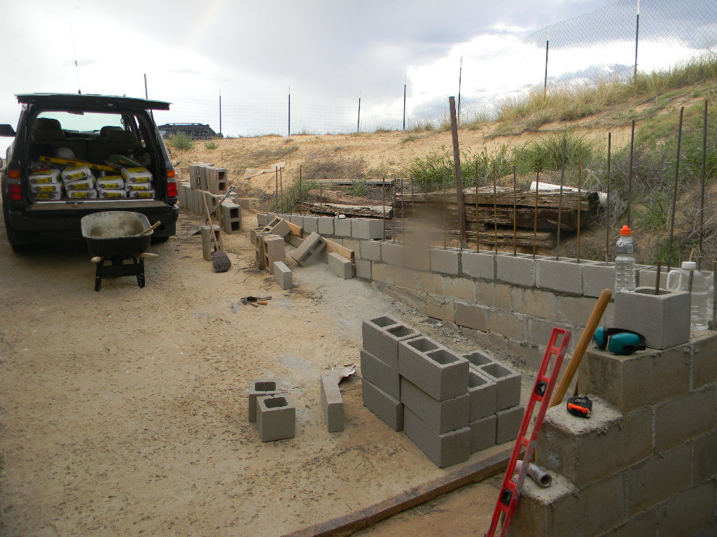
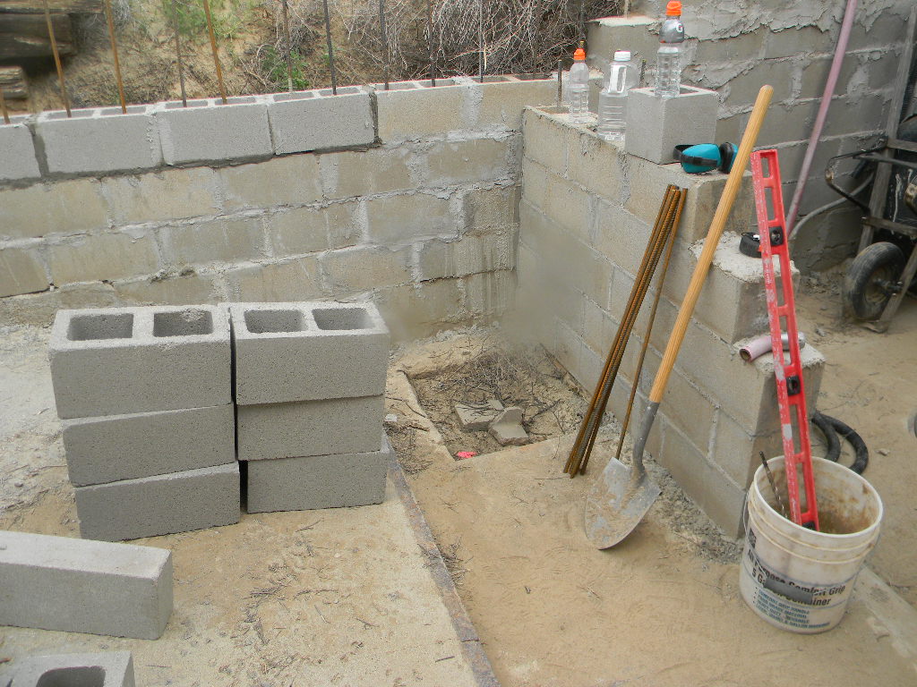
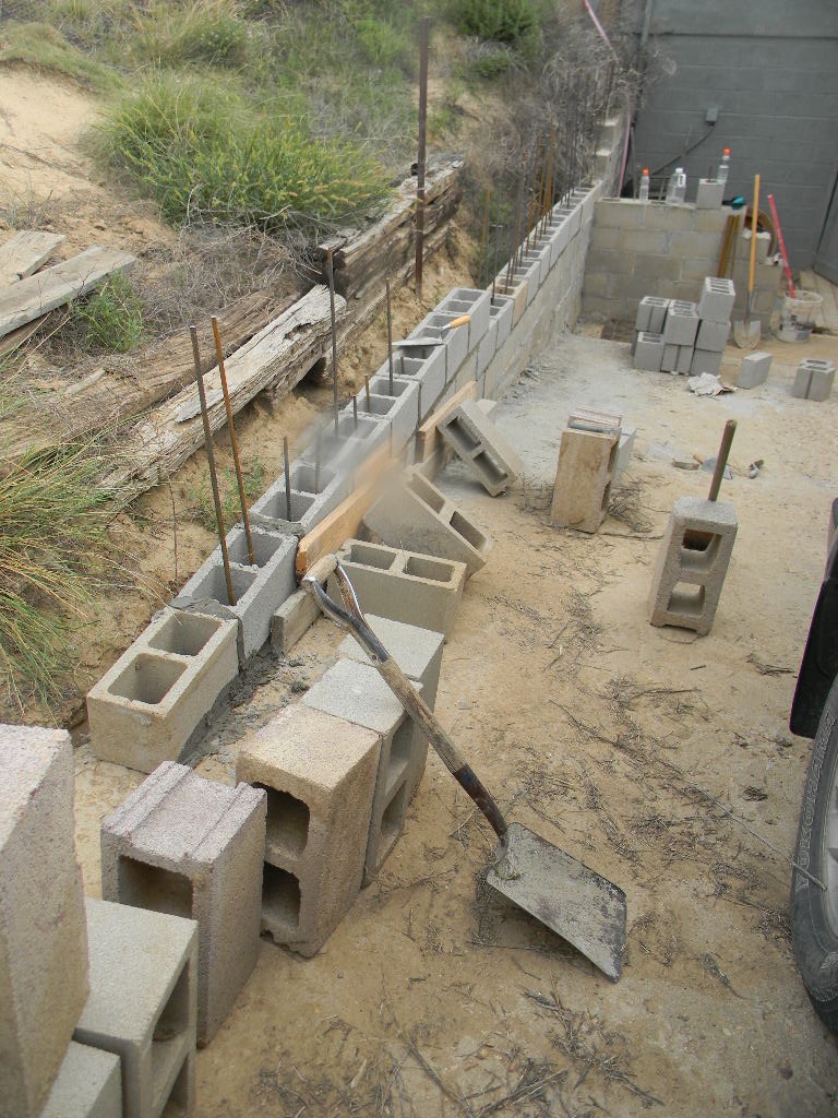
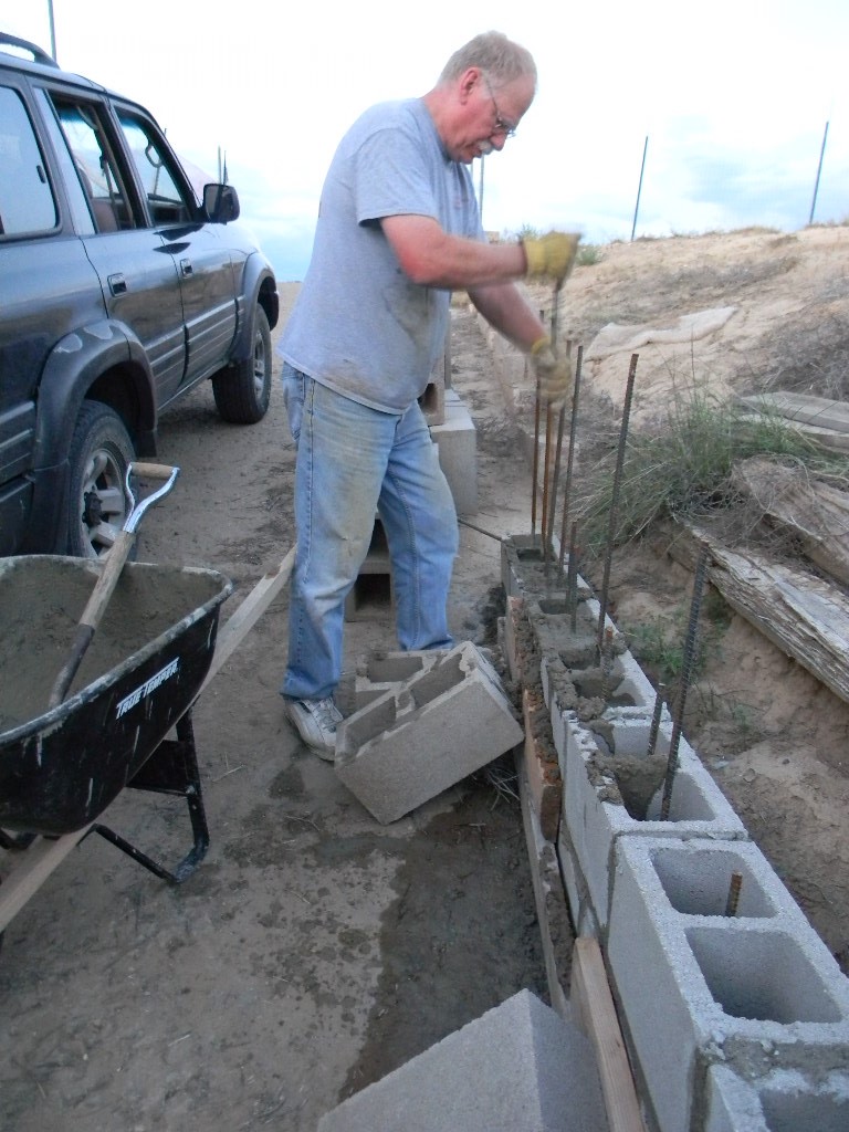
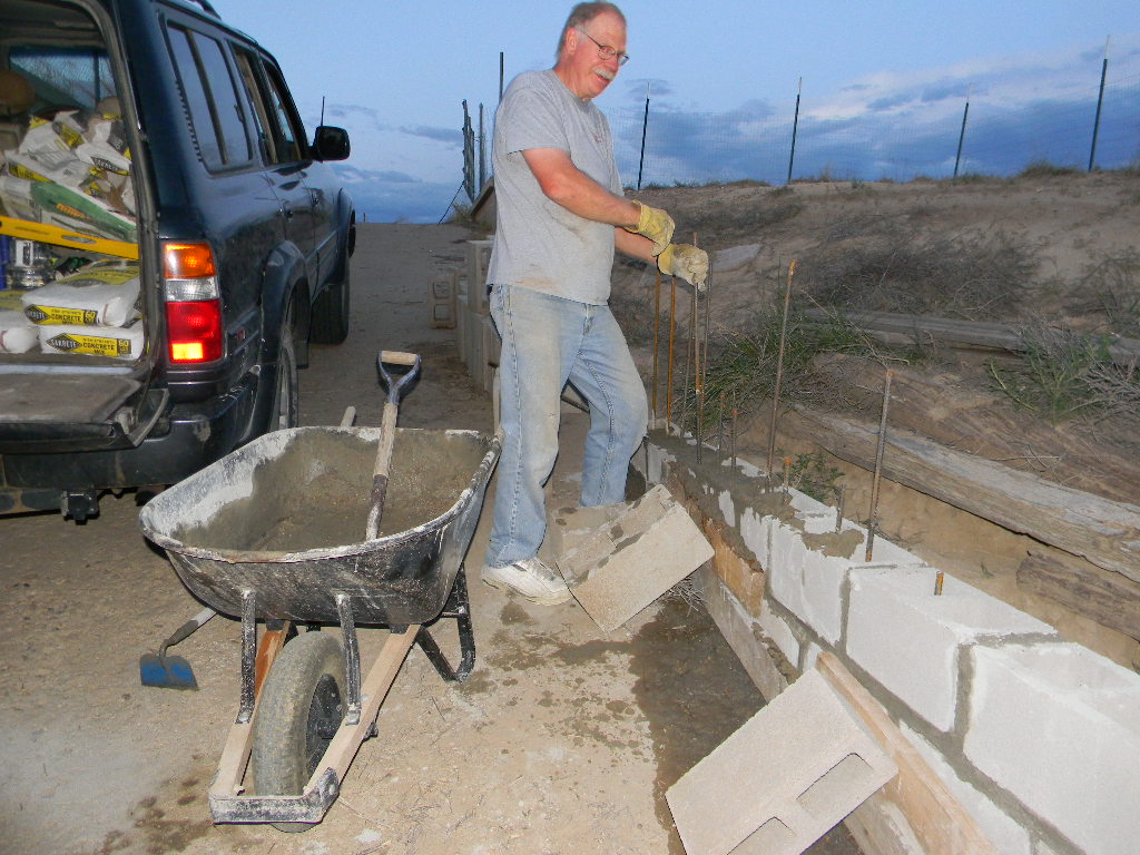
3. Dave brought 20 x 60-pound bags of cement, and used all of them to continue to repair/rebuild the ramp retaining wall. He made considerable progress extending the base of the wall. The higher the base of the wall reaches up the ramp, the less rain sediment will clog the sump pump. Dave stayed until late in the evening, until around sunset. Gary stayed with him and gave some help.
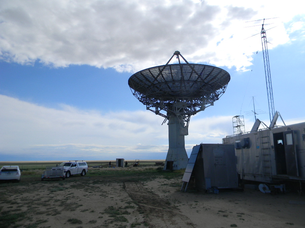
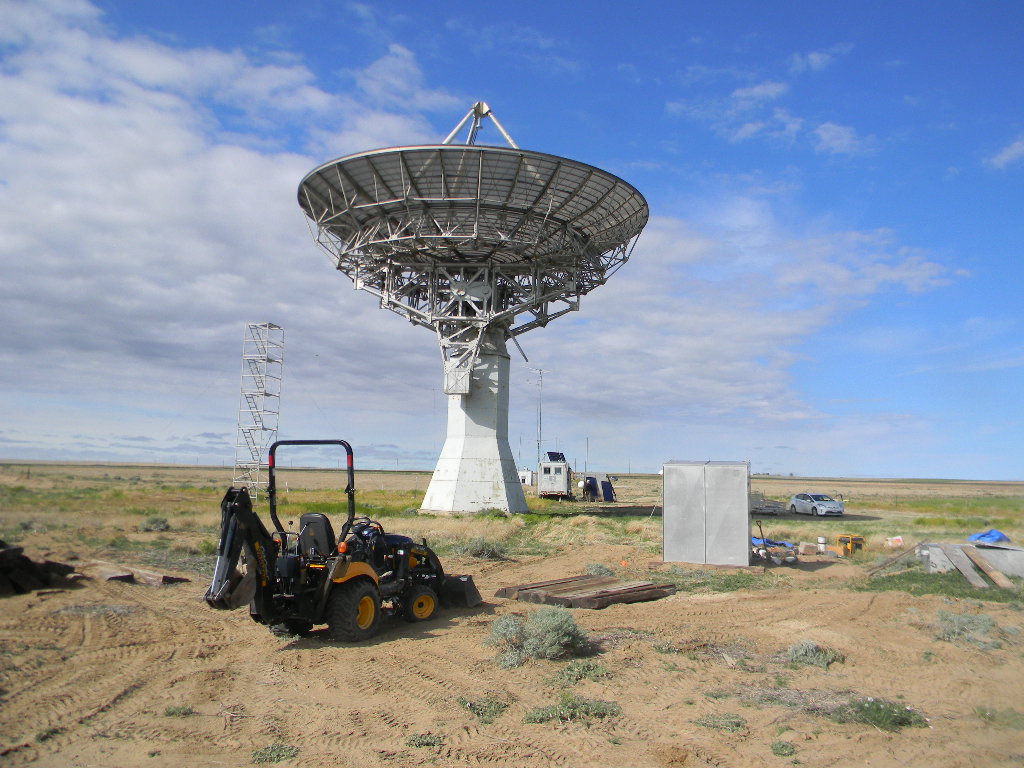
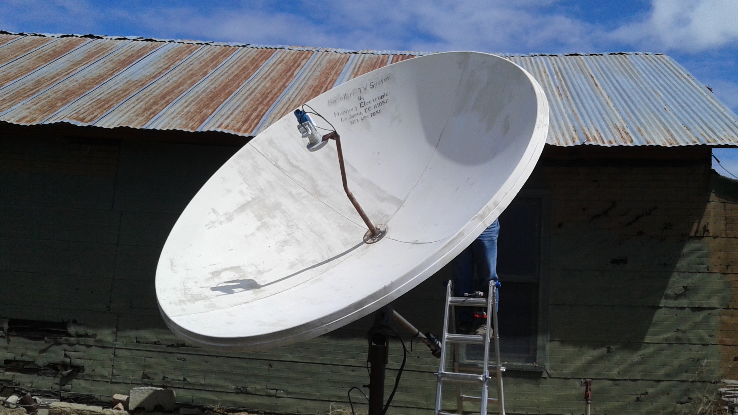
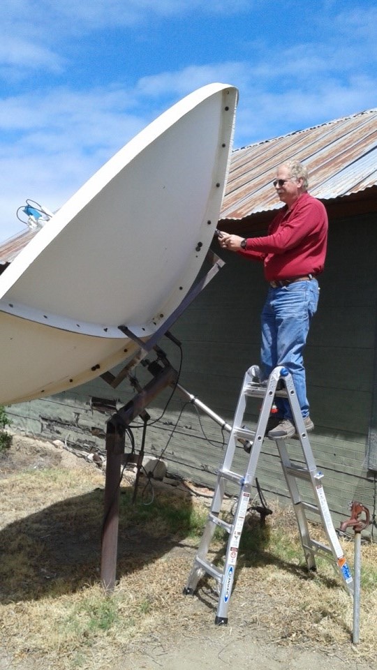
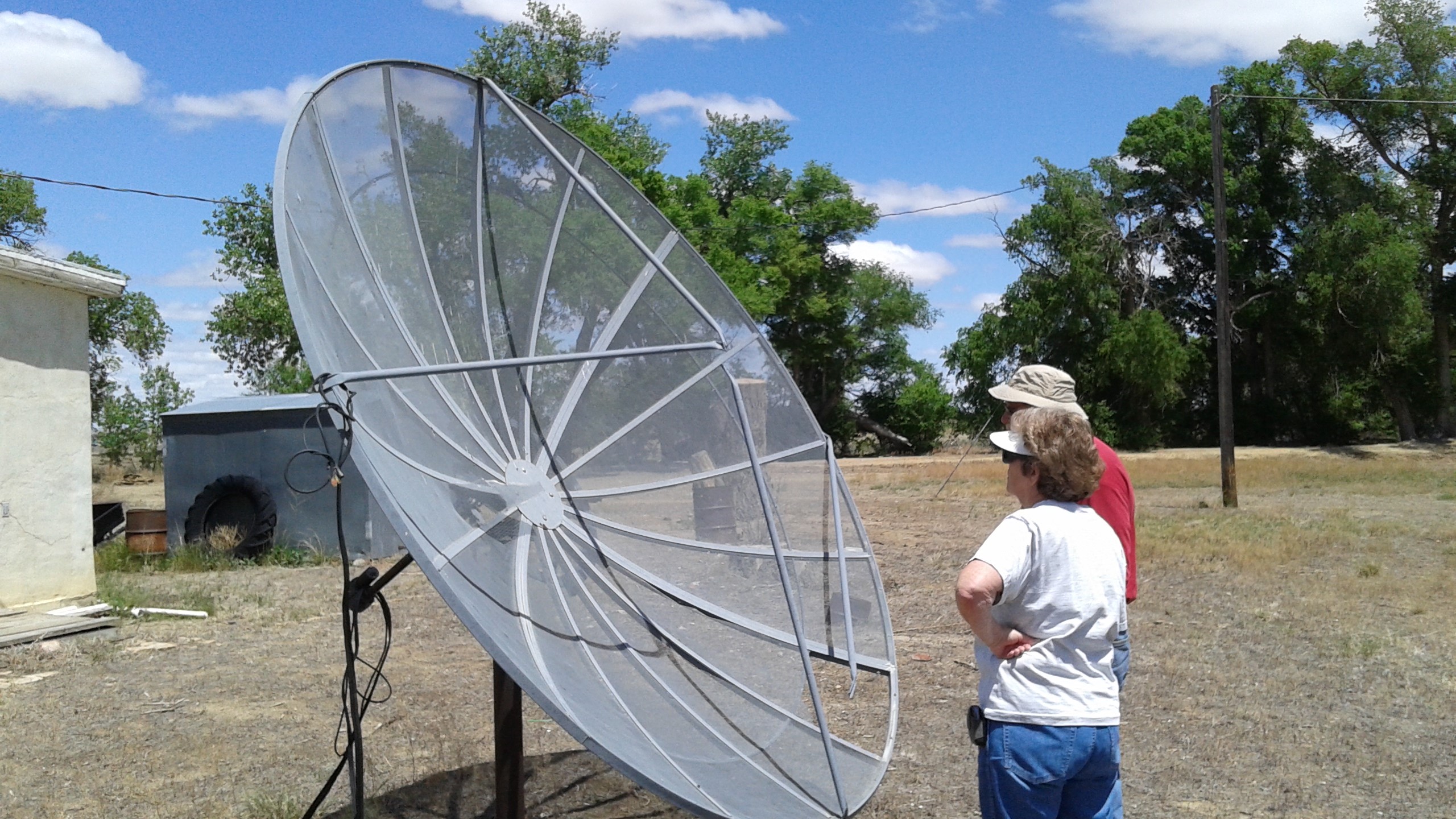
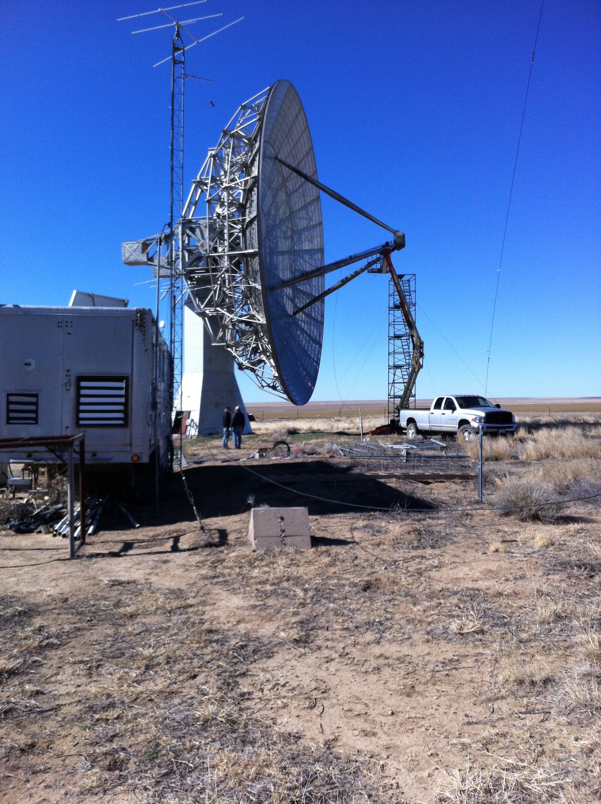
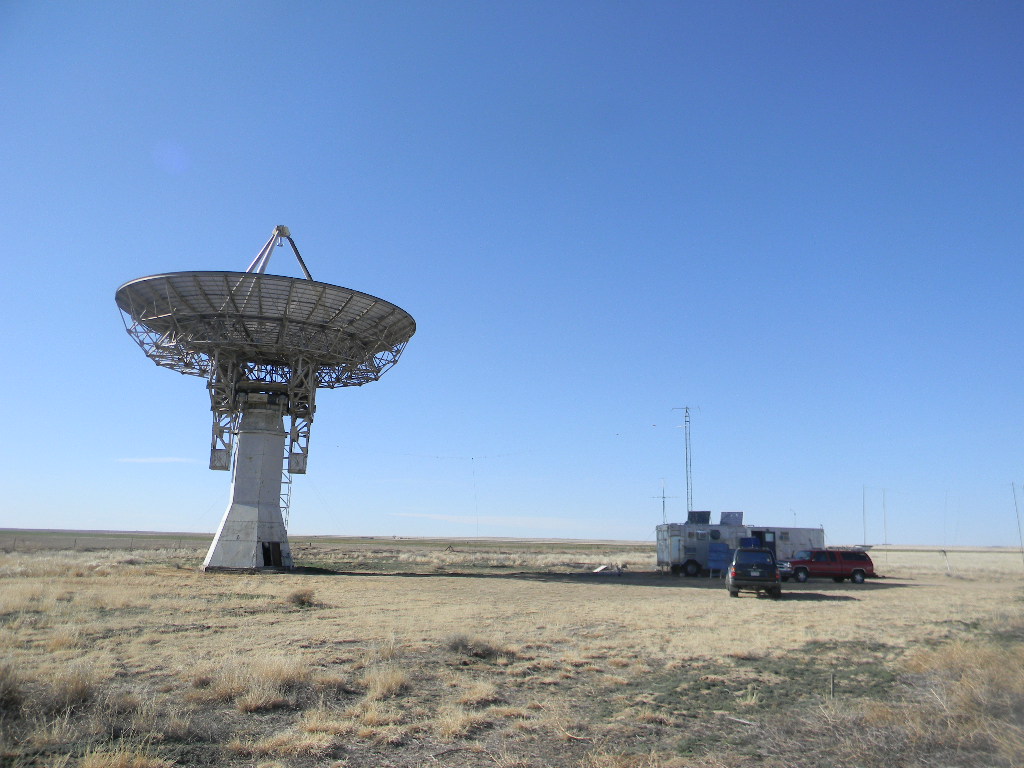
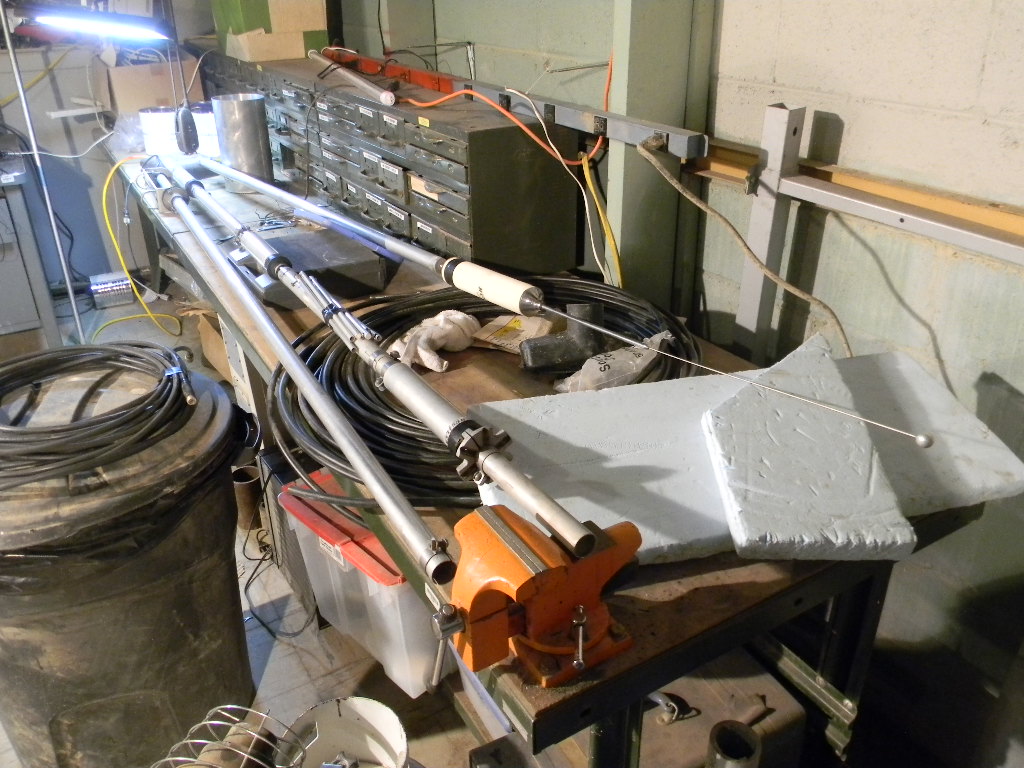
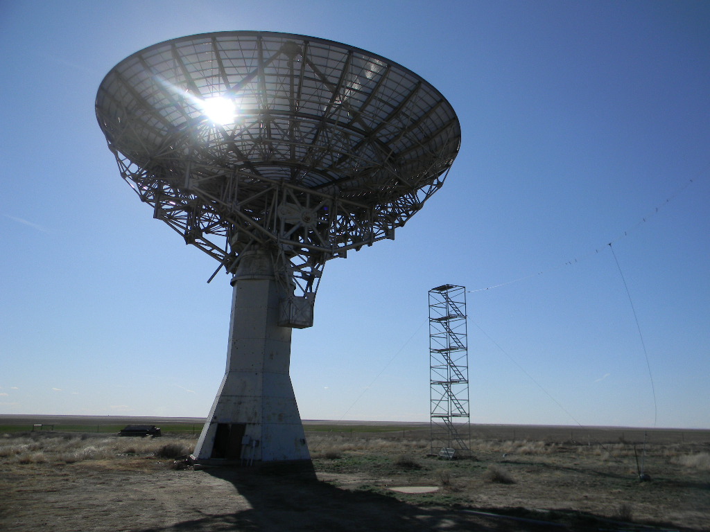
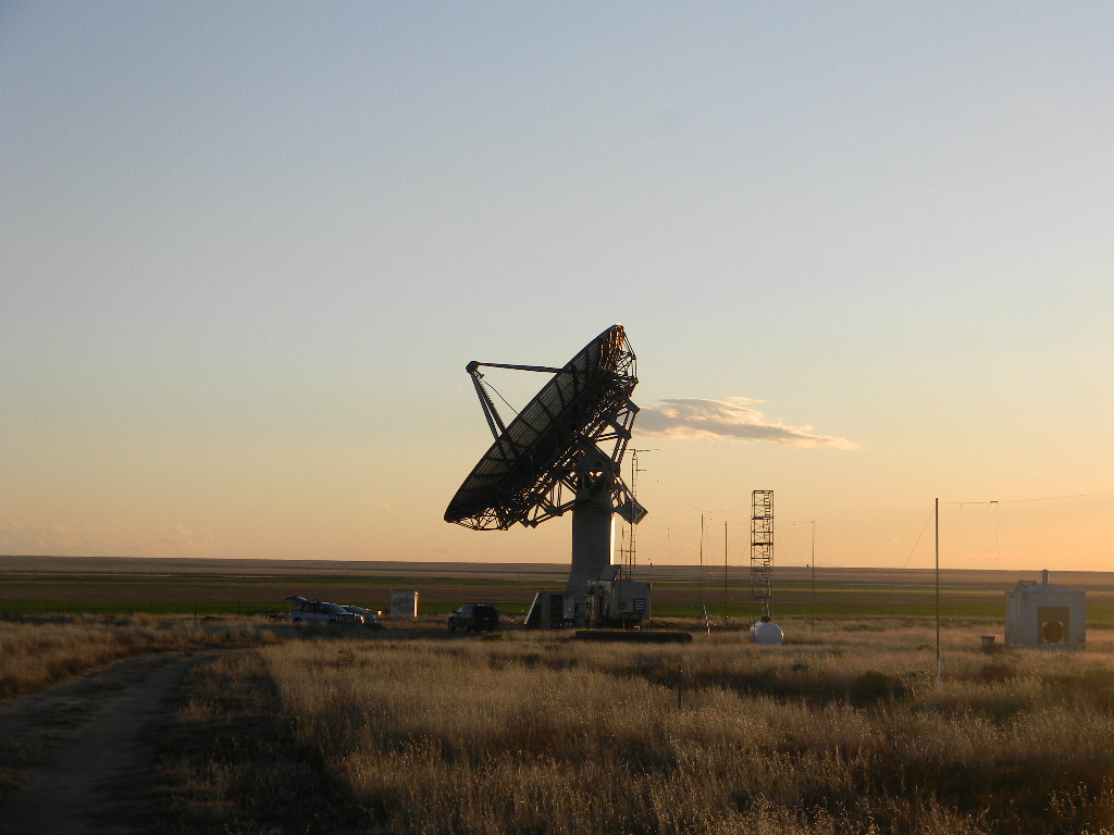
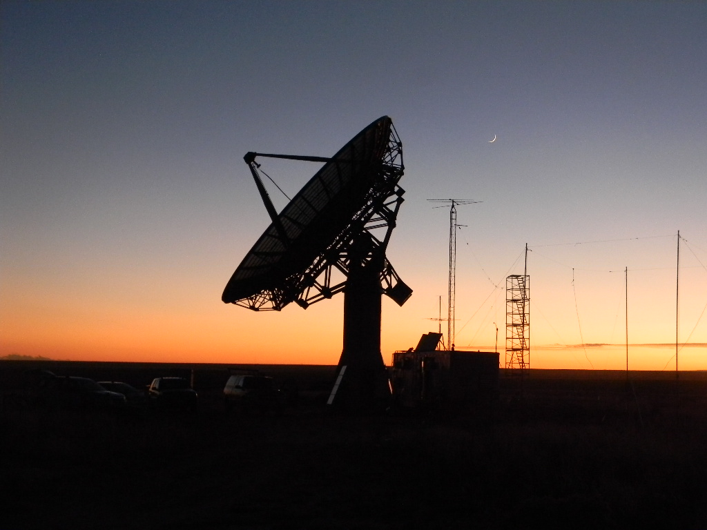
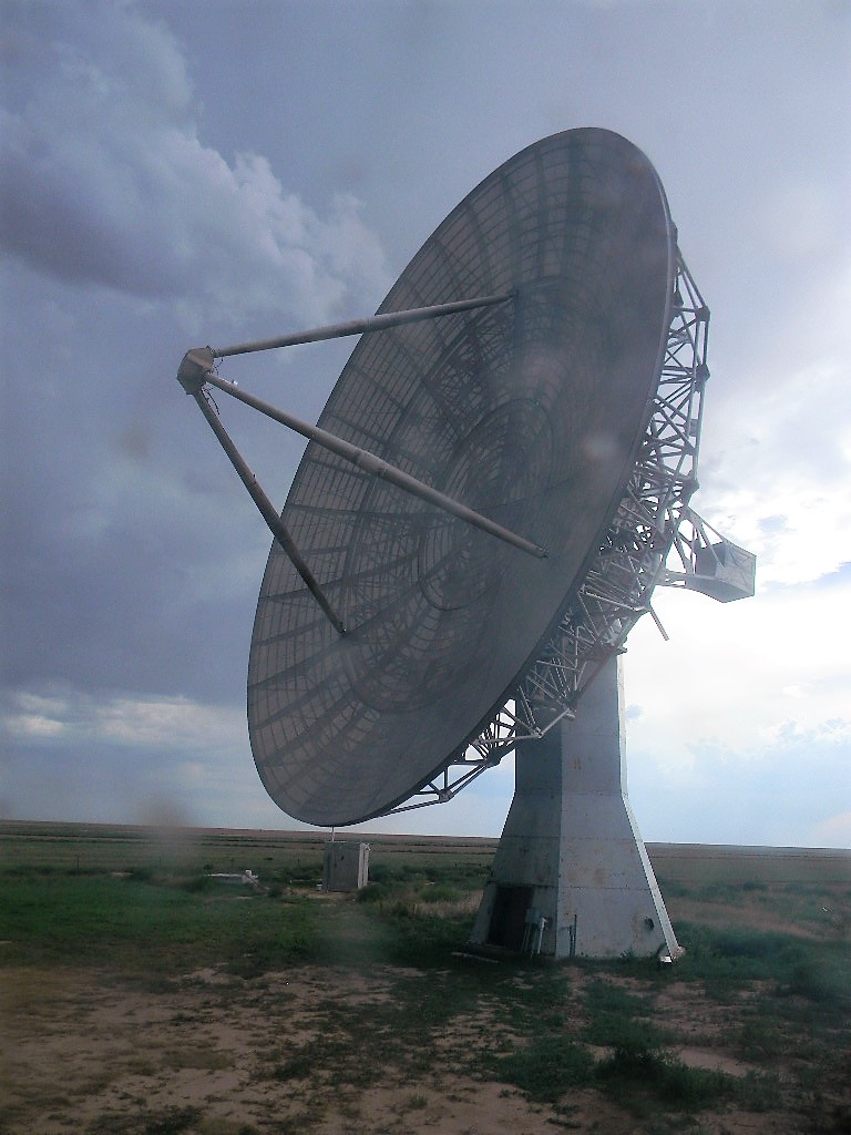
4. Rich brought the SpectraCyber 1420 MHz Hydrogen Line Spectrometer, and used it to continue to test the functioning and ability of the SpectraCyber together with the System 1 pointing system on the 60-foot antenna. Rich later showed Gary how to steer the dish antenna, and how to measure and record neutral hydrogen data. By the end of the day we located and measured several radio sources in the Sagitarius region. And we made a systematic scan almost perpendicular to the Milky Way galactic plane, in order to measure neutral hydrogen while pointing away from and in the plane. A more detailed discussion follows later in this post.
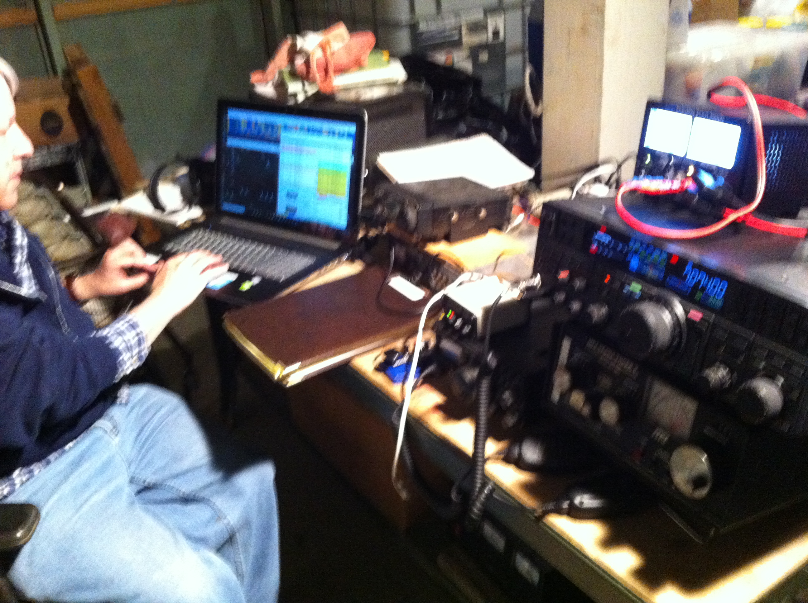
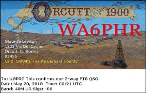
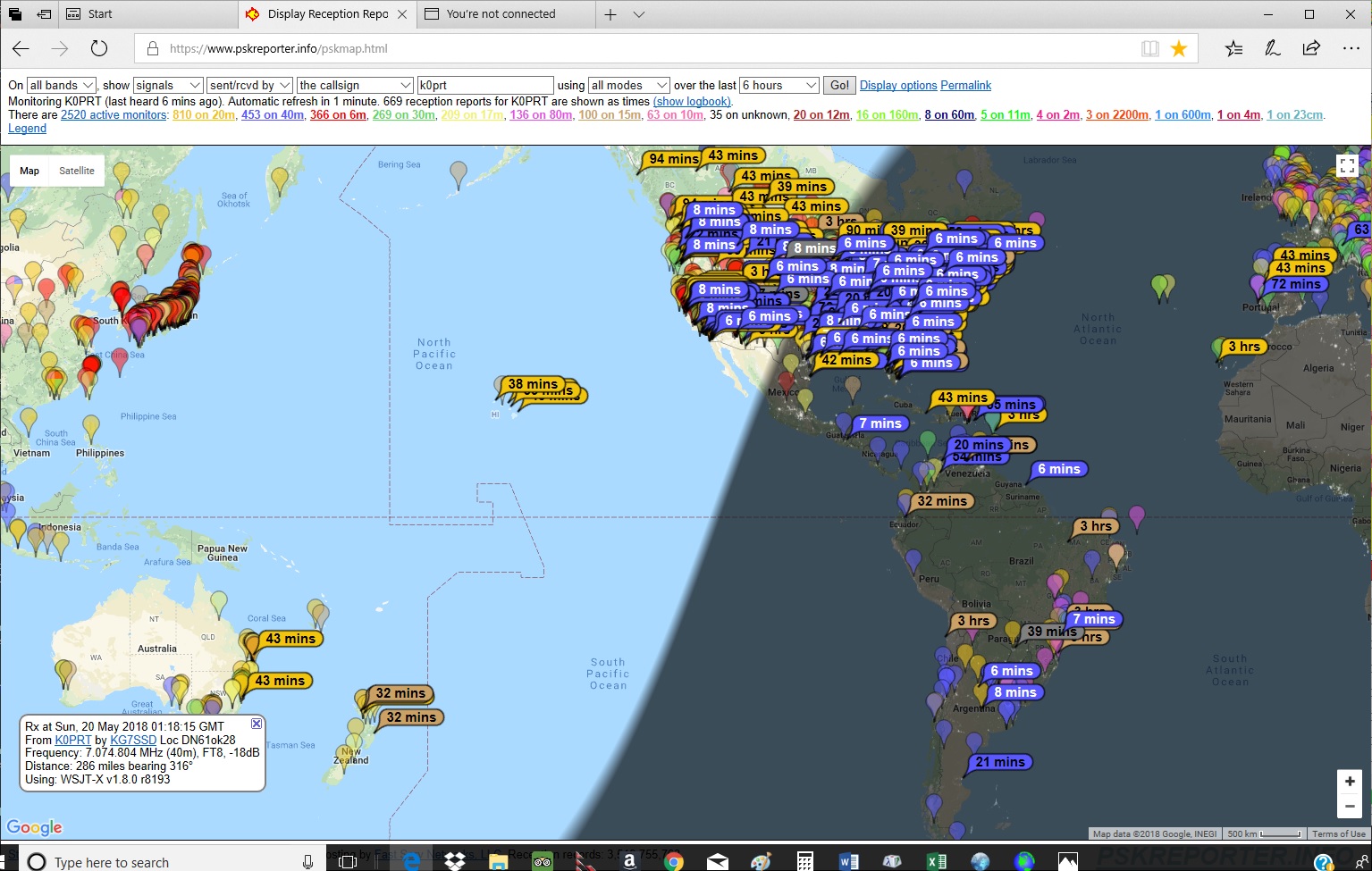
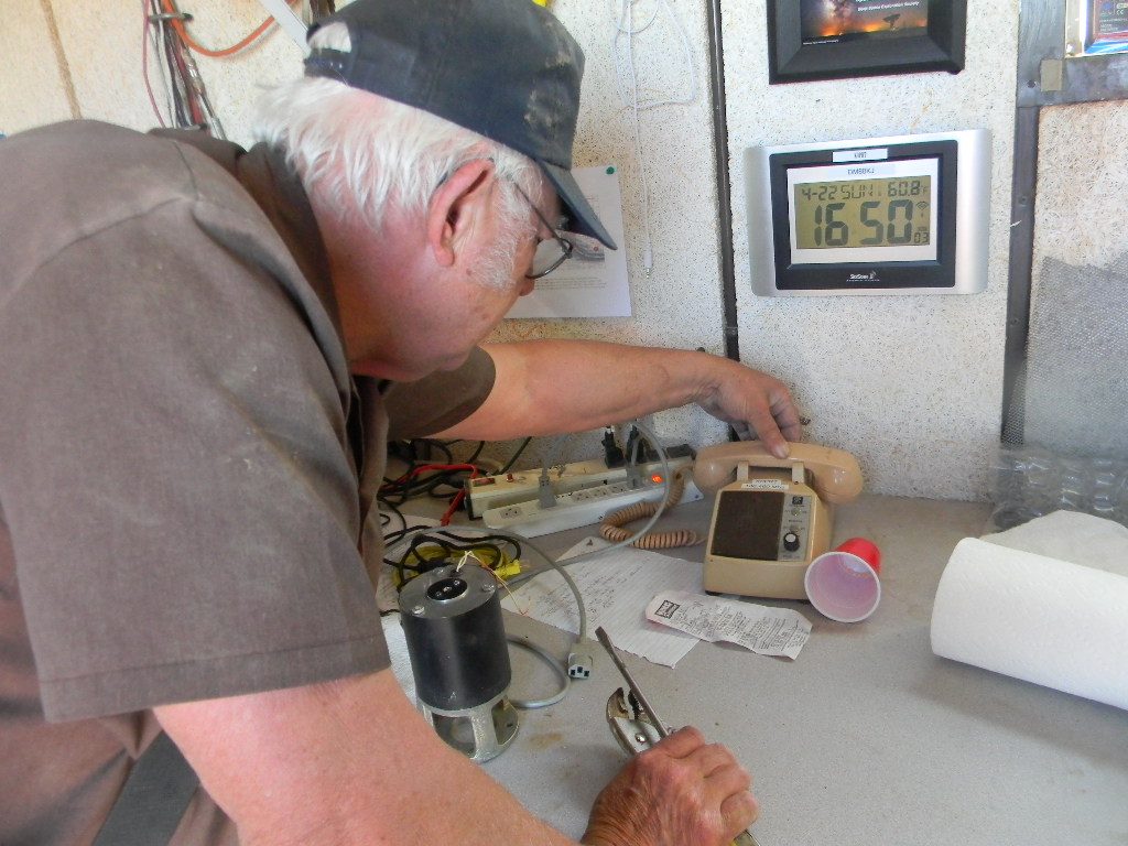
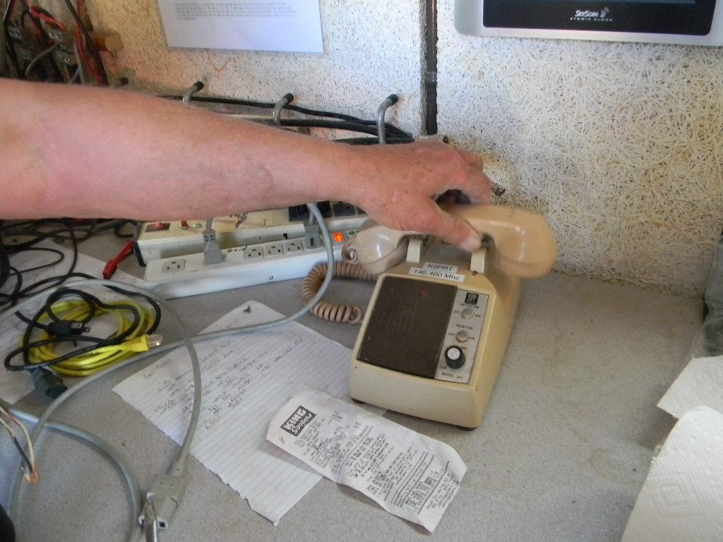
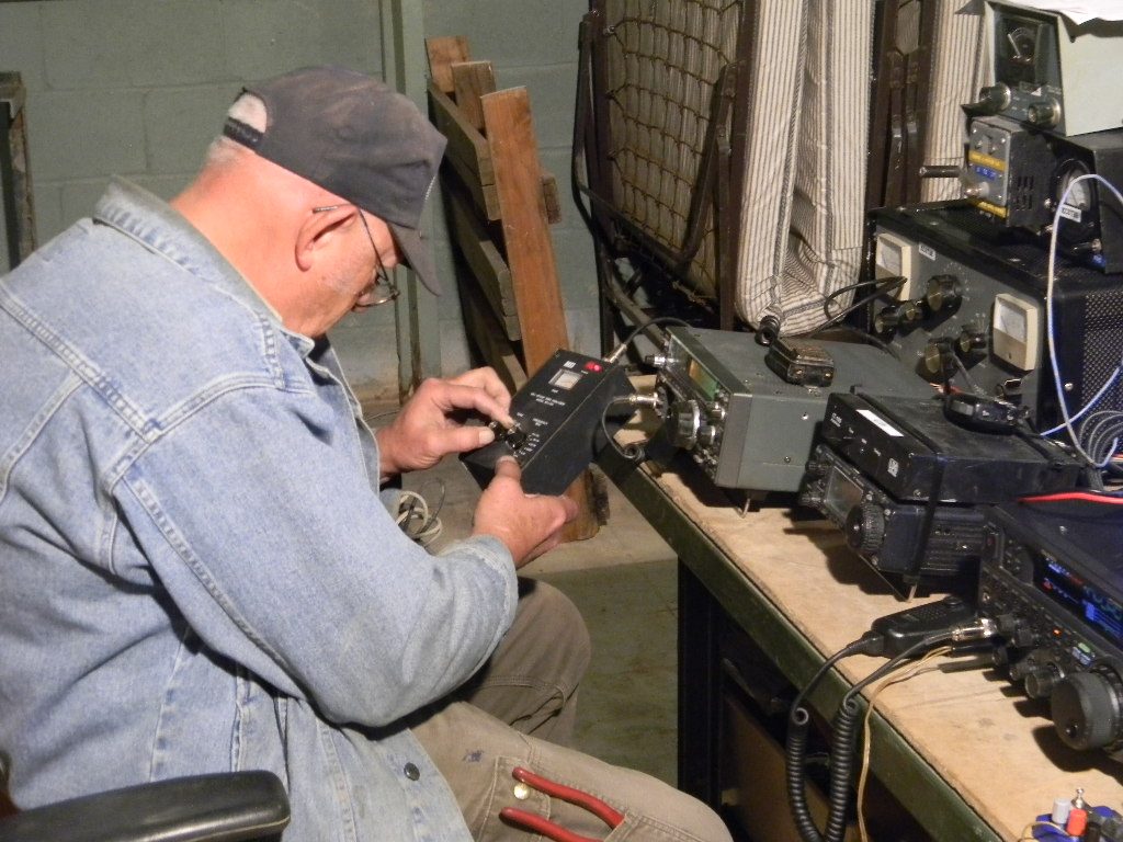
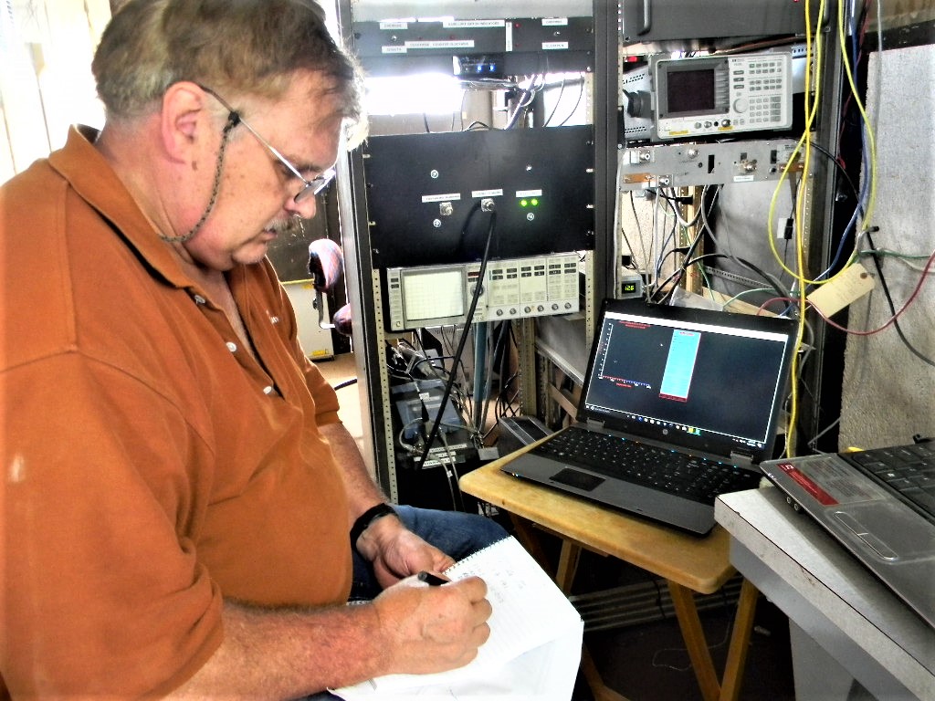
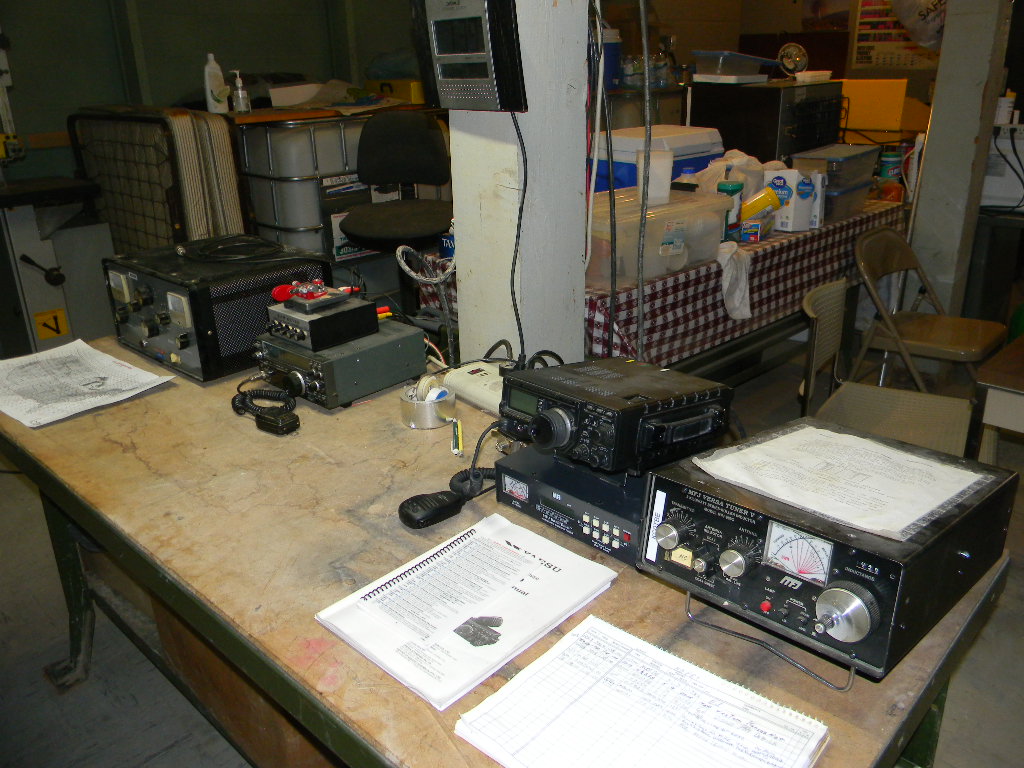
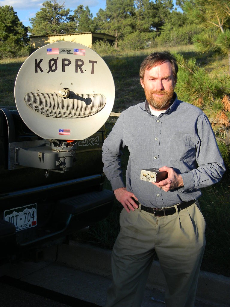
5. Gary tested the setup of the newly installed auto tuner for the FT-897 in the bunker ham station. With some adjusting and checking of cable connections, the tuner was found to be functioning OK. Gary took the opportunity to operate K0PRT in the QSO Parties this weekend for Kansas, Ohio, Hawaii, and for the US & Canadian islands, making about 30 contacts, on SSB and CW, on 40, 20, and 15 meters. Signal reports were mostly good, which seemed to indicate the combined FT-897 + tuner system is working OK. Gary wrote some Guidance Notes for using the tuner, and left those next to the tuner.
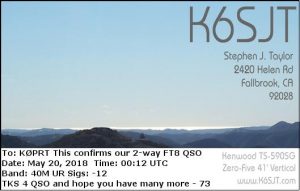
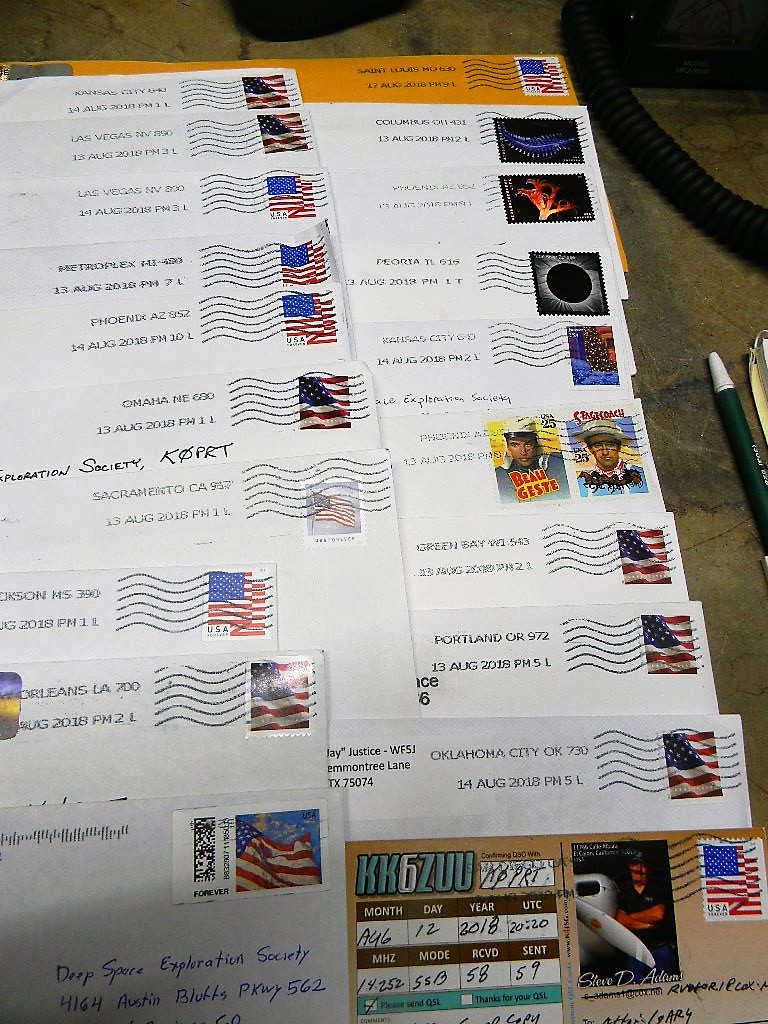
6. We received 20 QSL cards in the mail from the Open House special event station. Myron passed them on through Ed to Gary. Gary responded to all of them, and sent in the mail our QSL card responses to all by Monday.
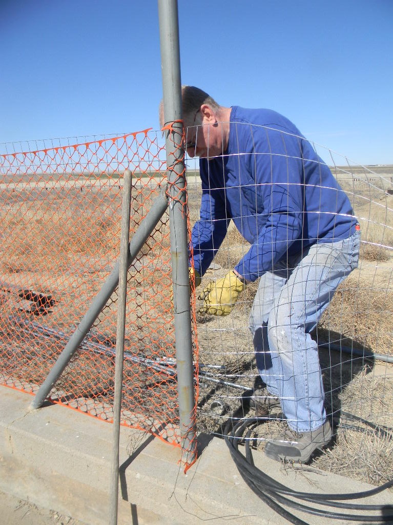
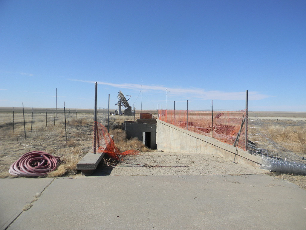
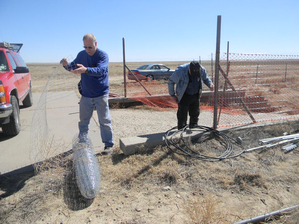
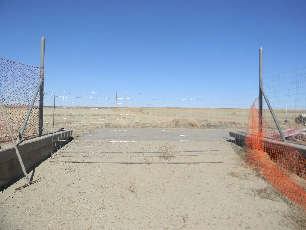
Next are some photos of our work. Then follows a more detailed discussion about the SpectraCyber observations with the 60-foot antenna.
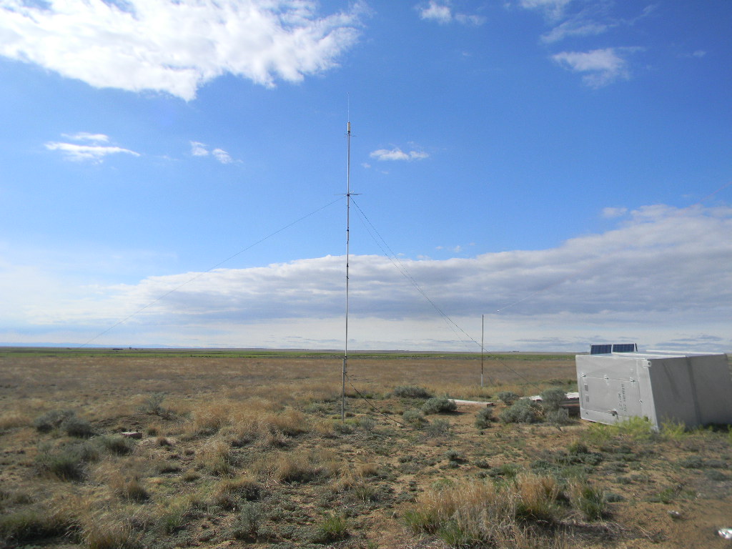
SpectraCyber observations with the 60-foot antenna
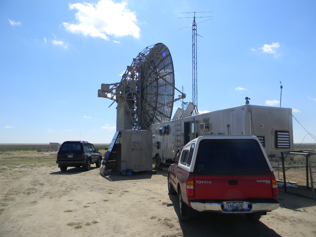
Rich brought the SpectraCyber 1420 MHz Hydrogen Line Spectrometer, to follow up on the successful observations we started to make with the 60-foot antenna during our Open House 2 weeks before. We used the System 1 pointing system. I later joined him by mid afternoon, after I finished my other work, and this is a report of what we did.
We started by searching for several sources with flux density values higher than 200 Janskies. However, at first no sources were found. The plane of the Milky Way was at that time very low along the southern horizon. There were few strong sources on our list available to look for at that time.
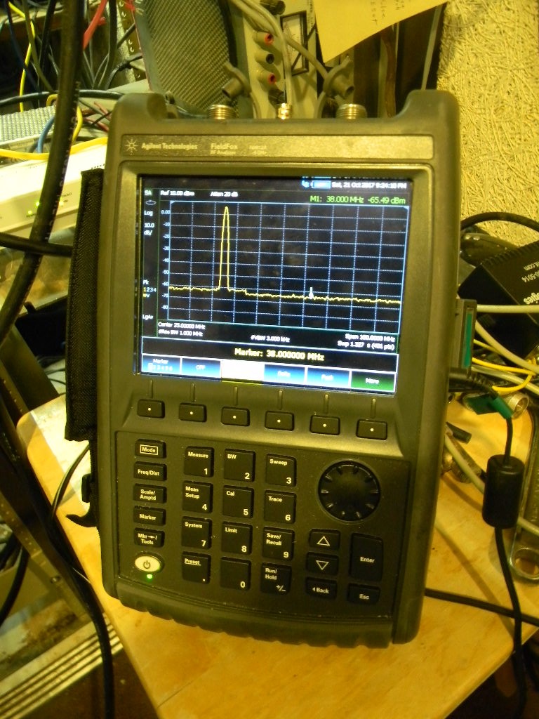
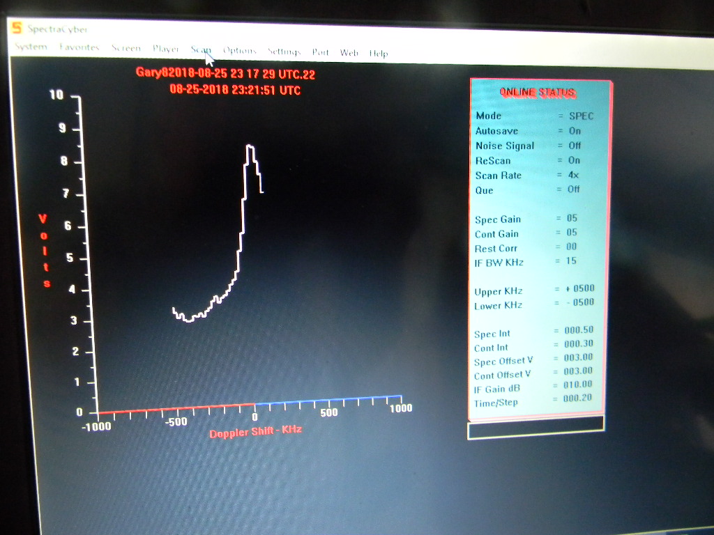
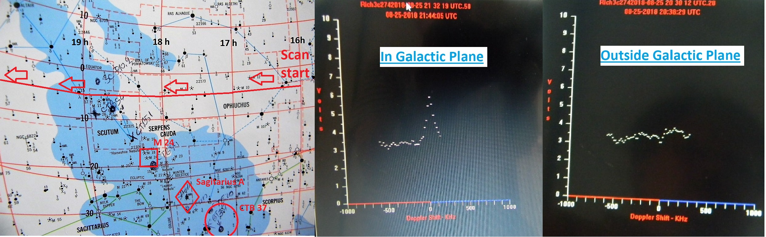
A little later, we just about ran into the Milky Way without looking for it, when the galactic plane rose higher. The signal trace of the SpectraCyber indicated the change: pointed away from the galactic plane, the signal trace stayed near about 3 volts, varying probably with noise, but not by more than a volt. Once pointing at the galactic plane, the voltage trace increased from about 5 to 7 volts (up to about 4 volts above the noise floor). The signal consistently showed a peak at about the center of the trace, at about the frequency of neutral hydrogen. We have not calibrated the SpectraCyber, and so we don’t exactly what frequency we were peaking. (The actual spectral line frequency is 1420.40575 MHz. And we may be seeing some doppler shift in our measurement.)
We then looked for several strong sources in the Sagitarius region, which by then had risen. We successfully found several, including:
- Sagitarius A, the center of our Milky Way galaxy. The radio emission is thought to be from the secondary effects of a black hole there.
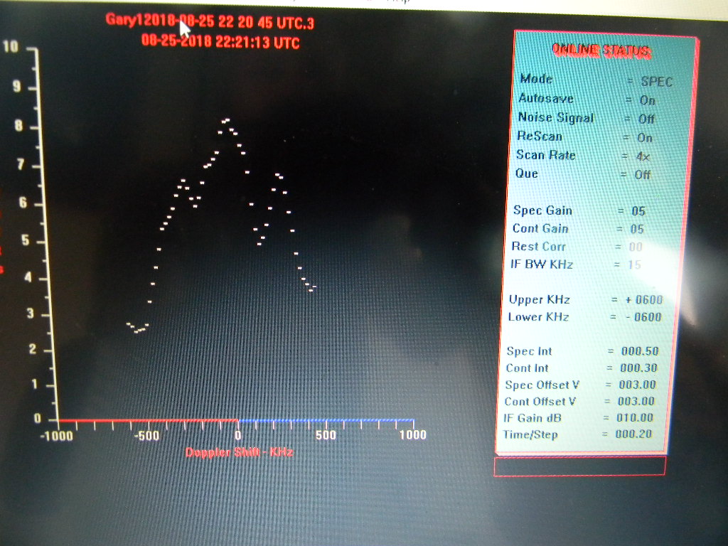
- CTB 37, a supernova remnant about 20,000 light years away (see https://www.nasa.gov/mission_pages/chandra/ctb-37a.html.) Our signal trace showed three peaks through most of our scans. Our interpretation is that the central peak is the original supernova remnant. The other peaks would be the doppler-shifted material outflowing away and towards us, following the supernova explosion.
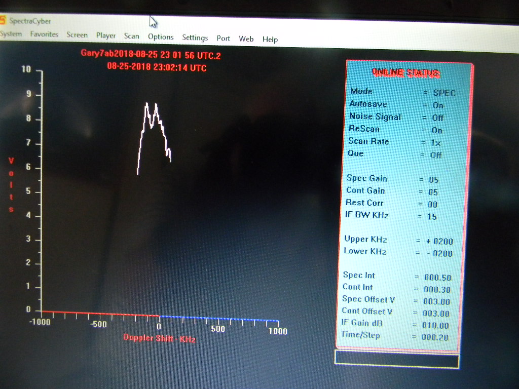
- The Sagitarius Star Cloud Messier 24, with a colder hydrogen cloud closer along the line of sight that absorbs some of the M24 hydrogen signal. This is the radio source Tony Bigbee pointed to during our Open House 2 weeks earlier. The signal trace has a distinctive dip, which had been identified in data from the Parkes Observatory in Australia. And as Tony has discussed, was used in the past by the RASDR2 team as an engineering detection test. The dip in signal is interpreted as a hydrogen cloud along the line of sight that is colder than the background source. It absorbs the background signal and then reradiates it out, but in all directions, hence the net signal to us is reduced. We used the RA & Dec location coordinates recorded during the Open House. We found the source again without difficulty.
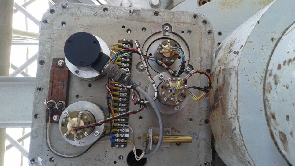
We used the System 1 computer display to read the angles our 60-foot antenna was pointed to. The display showed coordinates in both azimuth & elevation (Earth ground reference), and Right Ascension & Declination (celestial sky coordinate reference). We turned the antenna with the manual steering controls. At this time we do not have automatic tracking ability. But we were able to reasonably stay on our targets with continual manual adjustments. What we more often did was we found our source, then allowed the antenna to scan at the set elevation as the Earth rotated, and as a result get a short scan along a line of Declination. We then moved the elevation up and down slightly, to see differences in the scans a little north and south. We used this technique also to hone in on targets.
We then manually scanned across the Milky Way galactic plane, to obtain a slice from 16 to 20 hours Right Ascension, along the declination of -05 degrees. We stopped at intervals of 30 minutes Right Ascension (e.g., 17h 00 min, 17h 30 min, 18h 00 min, …), to let the SpectraCyber take full scans.
Our scan cut a steep acute angle through the width of the galactic plane, going across the constellations of Ophiuchus, the north edge of Scutum, and the southern part of Aquila. We therefore started and ended at angles pointed “above” and “below” from the galactic plane, and scanned across the galactic plane in between.
Since we were pointing to the southeast (and not due south), if we moved azimuth while maintaining elevation, the declination still changed. And so to keep on the -05 degree declination line, we had to adjust azimuth and elevation together.
DSES Science Meeting August 27, 2018 Follow Up
On the following Monday we had our monthly DSES Science Meeting at the home of Rich Russel.
At the meeting we discussed the observations we made with the 60-foot antenna two days earlier.
Tony Bigbee then also presented deeper details about his RASDR4 (Radio Astronomy Software Defined Radio). And he gave us more background about the earlier RASDR2 observations of Messier 24, with the dip in frequency. And he showed how he researched the earlier Parkes observatory data to find useable results and plots for us to compare to.
– 73, Gary Agranat, WA2JQZ